11.3.1.2 – CCNA Security Comprehensive Lab (Instructor Version)
Chapter 11 – CCNA Security Comprehensive Lab (Instructor Version)
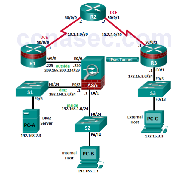
Topology
IP Addressing Table
| Device | Interface | IP Address | Subnet Mask | Default Gateway | Switch Port |
|---|---|---|---|---|---|
| R1 | G0/0 | 209.165.200.225 | 255.255.255.248 | N/A | ASA E0/0 |
| S0/0/0 (DCE) | 10.1.1.1 | 255.255.255.252 | N/A | N/A | |
| Loopback 1 | 172.20.1.1 | 255.255.255.0 | N/A | N/A | |
| R2 | S0/0/0 | 10.1.1.2 | 255.255.255.252 | N/A | N/A |
| S0/0/1 (DCE) | 10.2.2.2 | 255.255.255.252 | N/A | N/A | |
| R3 | G0/1 | 172.16.3.1 | 255.255.255.0 | N/A | S3 F0/5 |
| S0/0/1 | 10.2.2.1 | 255.255.255.252 | N/A | N/A | |
| S1 | VLAN 1 | 192.168.2.11 | 255.255.255.0 | 192.168.2.1 | N/A |
| S2 | VLAN 1 | 192.168.1.11 | 255.255.255.0 | 192.168.1.1 | N/A |
| S3 | VLAN 1 | 172.16.1.11 | 255.255.255.0 | 172.30.3.1 | N/A |
| ASA | VLAN 1 (E0/1) | 192.168.1.1 | 255.255.255.0 | N/A | S2 F0/24 |
| VLAN 2 (E0/0) | 209.165.200.226 | 255.255.255.248 | N/A | R1 G0/0 | |
| VLAN 2 (E0/2) | 192.168.2.1 | 255.255.255.0 | N/A | S1 F0/24 | |
| PC-A | NIC | 192.168.2.3 | 255.255.255.0 | 192.168.2.1 | S1 F0/6 |
| PC-B | NIC | 192.168.1.3 | 255.255.255.0 | 192.168.1.1 | S2 F0/18 |
| PC-C | NIC | 172.16.3.3 | 255.255.255.0 | 172.16.3.1 | S3 F0/18 |
Objectives
Part 1: Create a Basic Technical Security Policy
Part 2: Configure Basic Device Settings
Part 3: Configure Secure Router Administrative Access
• Configure encrypted passwords and a login banner.
• Configure the EXEC timeout value on console and VTY lines.
• Configure login failure rates and VTY login enhancements.
• Configure Secure Shell (SSH) access and disable Telnet.
• Configure local authentication, authorization, and accounting (AAA) user authentication.
• Secure the router against login attacks, and secure the IOS image and the configuration file.
• Configure a router NTP server and router NTP clients.
• Configure router syslog reporting and a syslog server on a local host.
Part 4: Configure a Zone-Based Policy Firewall and Intrusion Prevention System
• Configure a Zone-Based Policy Firewall (ZPF) on an ISR using the CLI.
• Configure an intrusion prevention system (IPS) on an ISR using the CLI.
Part 5: Secure Network Switches
• Configure passwords and a login banner.
• Configure management VLAN access.
• Secure access ports.
• Protect against Spanning Tree Protocol (STP) attacks.
• Configure port security and disable unused ports.
Part 6: Configure ASA Basic Settings and Firewall
• Configure basic settings, passwords, date, and time.
• Configure the inside and outside VLAN interfaces.
• Configure port address translation (PAT) for the inside network.
• Configure a Dynamic Host Configuration Protocol (DHCP) server for the inside network.
• Configure administrative access via Telnet and SSH.
• Configure a static default route for the Adaptive Security Appliance (ASA).
• Configure Local AAA user authentication.
• Configure a DMZ with a static NAT and ACL.
• Verify address translation and firewall functionality.
Part 7 Configure a DMZ, Static NAT, and ACLs on an ASA
Part 8: Configure ASA Clientless SSL VPN Remote Access Using ASDM
• Configure a remote access SSL VPN using the Cisco Adaptive Security Device Manager (ASDM).
• Verify SSL VPN access to the portal.
Part 9: Configure a Site-to-Site VPN between the ASA and ISR
• Configure an IPsec site-to-site VPN between the ASA and R3 using ASDM and the CLI.
• Activate and verify the IPsec site-to-site VPN tunnel between the ASA and R3.
Background/Scenario
This comprehensive lab is divided into nine parts. The parts should be completed sequentially. In Part 1, you will create a basic technical security policy. In Part 2, you will configure the basic device settings. In Part 3, you will secure a network router using the command-line interface (CLI) to configure IOS features, including AAA and SSH. In Part 4, you will configure a ZPF and IPS on an ISR. In Part 5, you will configure a network switch using the CLI. In Parts 7 and 8, you will configure the ASA firewall functionality and clientless SSL VPN remote access. In Part 9, you will configure a site-to-site VPN between the ASA and R3.
Note: The router commands and output in this lab are from a Cisco 1941 router with Cisco IOS Release 15.4(3)M2 (with a Security Technology Package license). The switch commands and output are from Cisco WS-C2960-24TT-L switches with Cisco IOS Release 15.0(2)SE4 (C2960-LANBASEK9-M image). Other routers, switches, and Cisco IOS versions can be used. See the Router Interface Summary Table at the end of the lab to determine which interface identifiers to use based on the equipment in the lab. Depending on the router, or switch model and Cisco IOS version, the commands available and the output produced might vary from what is shown in this lab.
The ASA used with this lab is a Cisco model 5505 with an 8-port integrated switch, running OS version 9.2(3) and the Adaptive Security Device Manager (ASDM) version 7.4(1) and comes with a Base license that allows a maximum of three VLANs.
Note: Before beginning, ensure that the routers and switches have been erased and have no startup configurations.
Instructor Note: Instructions for initializing the ASA, switches, and routers are provided in Chapter 0.0.0.0.
Required Resources
• 1 ASA 5505 (OS version 9.2(3) and ASDM version 7.4(1) and Base license or comparable)
• 3 routers (Cisco 1941 with Cisco IOS Release 15.4(3)M2 image with a Security Technology package
license)
• 3 switches (Cisco 2960 or comparable) (not required)
• 3 PCs (Windows 7 or Windows 8.1, SSH Client, and WinRadius)
• Serial and Ethernet cables, as shown in the topology
• Console cables to configure Cisco networking devices
Part 1: Create a Basic Technical Security Policy (Chapters 1 and 11)
In Part 1, you will create a Network Device Security Guidelines document that can serve as part of a comprehensive network security policy. This document addresses specific router and switch security measures and describes the security requirements to be implemented on the infrastructure equipment.
Task 1: Identify Potential Sections of a Basic Network Security Policy.
A network security policy should include several key sections that can address potential issues for users, network access, device access, and other areas. List some key sections you think could be part of a basicsecurity policy.
_______________________________________________________________________________________
_______________________________________________________________________________________
_______________________________________________________________________________________
_______________________________________________________________________________________
Answers will vary but could include the following:
• Introduction
• Acceptable Use Policy
• E-mail and Communications Activities
• Antivirus Policy
• Identity Policy
• Password Policy
• Encryption Policy
• Remote Access Policy
• Virtual Private Network (VPN) Policy
• Extranet Policy
• Device Management Policy
• Physical Device Security Policy
Task 2: Create a “Network Equipment Security Guidelines” Document As a Supplement to a Basic Security Policy
Step 1: Review the objectives from previous CCNA Security labs.
a. Open each of the labs completed from chapters 1 to 9, and review the objectives listed for each one.
b. Copy the objectives to a separate document and use it as a starting point. Focus on the objectives that involve security practices and device configuration.
Step 2: Create a “Network Device Security Guidelines” document for router and switch security.
Create a high-level list of tasks to include for network access and device security. This document should reinforce and supplement the information presented in a basic security policy. It is based on the content of previous CCNA Security labs and on the networking devices present in the course lab topology.
Note: The “Network Device Security Guidelines” document should be no more than two pages, and will be the basis for the equipment configuration in the remaining parts of the lab.
Step 3: Submit the “Network Device Security Guidelines” to your instructor.
Provide the “Network Device Security Guidelines” document to your instructor for review before starting Part 2 of this lab. You can send the document as an e-mail attachment or put it on removable storage media, such as a flash drive.
Instructor Note: The following is an example of how the “Network Device Security Guidelines” document
might look. Ensure that the students have addressed the categories and steps shown here.
Technical Policies Supplement to Security Policies
Network Device Security Guidelines
Unless otherwise indicated, these policy guidelines apply to all primary network devices, such as switches and routers.
Router Administrative Access
The following steps must be taken to secure and harden routers:
1) Configure the enable secret, console, and VTY passwords.
2) Encrypt all passwords with the highest level of encryption available. Passwords should be a minimum of 10 characters and include a combination of uppercase letters, lowercase letters, numbers, and special characters.
3) Configure a login banner that warns unauthorized users of the penalties of accessing this device.
4) Configure a local database administrative user with privilege level 15 and a secret password.
5) Configure an SSH server and disable Telnet access.
6) Configure a centralized synchronized time source using NTP with authentication.
7) Configure syslog support on edge routers.
8) Enable HTTP secure server for web-based access.
9) Configure centralized authentication for each site using AAA and RADIUS.
10) Disable unnecessary services.
11) Configure static routing between edge routers and the ISP.
Router Firewalls and Intrusion Prevention
Configure a ZPF on edge routers. The firewall must allow external SSH connections, VPN traffic, and NTP.
Configure a Cisco IOS IPS on the internal and external interfaces of the edge router.
Switch Security Measures
The following steps should be taken to secure and harden switches:
1) Configure the enable secret, console, and VTY passwords.
2) Encrypt all passwords with the highest level of encryption available. Passwords should be a minimum of 10 characters and include a combination of uppercase letters, lowercase letters, numbers, and special characters.
3) Configure a login banner that warns unauthorized users of the penalties of accessing this device.
4) Configure a local database administrative user with privilege level 15 and a secret password.
5) Configure NTP with authentication to access a centralized synchronized time source.
6) Configure an SSH server and disable Telnet access.
7) Disable the HTTP server.
8) Configure centralized authentication using AAA and RADIUS.
9) Configure forced trunking mode on trunk ports.
10) Change the native VLAN for trunk ports to an unused VLAN.
11) Enable storm control for broadcasts.
12) Configure all active non-trunk ports as access ports.
13) Enable PortFast, BPDU guard, and loop guard on appropriate active ports.
14) Configure port security.
15) Disable unused ports.
Device Operating System and Configuration File Security
1) Back up the device’s IOS images to a TFTP server.
2) Back up the device’s running configs to a TFTP server.
3) Secure the Cisco IOS image and configuration files.
VPN Remote Access
1) Configure corporate router support for remote access IPsec VPN connections.
2) Provide the Cisco VPN Client on external hosts.
Part 2: Configure Basic Device Settings (Chapters 2 and 6)
Step 1: Cable the network as shown in the topology.
Attach the devices, as shown in the topology diagram, and cable as necessary.
Step 2: Configure basic settings for all routers.
a. Configure hostnames, as shown in the topology.
b. Configure the interface IP addresses, as shown in the IP addressing table.
c. Configure a serial interface DCE clock rate of 128000 for the routers, if using routers other than those specified with this lab.
Instructor Note: The Cisco ISR 1941 IOS and WICs used in this lab will auto configure the clock rate on serial DCE interfaces and set it to 2000000.
d. Disable DNS lookup on each router.
R1(config)# no ip domain-lookup
Step 3: Configure static default routes on R1 and R3.
a. Configure a static default route from R1 to R2 and from R3 to R2.
R1(config)# ip route 0.0.0.0 0.0.0.0 10.1.1.2

R3(config)# ip route 0.0.0.0 0.0.0.0 10.2.2.2
b. Configure static routes from R2 to the R1 simulated LAN (Loopback 1), the R1 Fa0/0-to-ASA subnet, and the R3 LAN.
R2(config)# ip route 172.16.3.0 255.255.255.0 10.2.2.1
R2(config)# ip route 209.165.200.224 255.255.255.248 10.1.1.1
Step 4: Configure basic settings for each switch.
a. Configure hostnames, as shown in the topology.
b. Configure the VLAN 1 management address on each switch, as shown in the IP Addressing table.
S1(config)# interface vlan 1
S1(config)# ip address 192.168.2.11 255.255.255.0
S1(config)# no shutdown

S2(config)# interface vlan 1
S2(config)# ip address 192.168.1.11 255.255.255.0
S2(config)# no shutdown

S3(config)# interface vlan 1
S3(config)# ip address 172.16.3.11 255.255.255.0
S3(config)# no shutdown
c. Configure the IP default gateway for each of the three switches.
S1(config)# ip default-gateway 192.168.2.1

S2(config)# ip default-gateway 192.168.1.1

S3(config)# ip default-gateway 172.16.3.1
d. Disable DNS lookup on each switch.
S1(config)# no ip domain-lookup
Step 5: Configure PC host IP settings.
Configure a static IP address, subnet mask, and default gateway for each PC, as shown in the IP Addressing table.
Step 6: Verify connectivity between PC-C and R1 G0/0.
PC-C:\> ping 209.165.200.225
Step 7: Save the basic running configuration for each router and switch.
Part 3: Configure Secure Router Administrative Access (Chapters 2 and 3)
You will use the CLI to configure passwords and device access restrictions.
Task 1: Configure Settings for R1 and R3
Step 1: Configure a minimum password length of 10 characters.
R1(config)# security passwords min-length 10
Step 2: Encrypt plaintext passwords.
R1(config)# service password-encryption
Step 3: Configure a login warning banner.
Configure a warning to unauthorized users with a message-of-the-day (MOTD) banner that says:
Unauthorized access strictly prohibited and prosecuted to the full extent of the law!.
R1(config)# banner motd $Unauthorized access strictly prohibited!$
Step 4: Configure the enable secret password.
Use cisco12345 as the enable secret password. Use the strongest encryption type available.
R1(config)# enable algorithm-type scrypt secret cisco12345
Step 5: Configure the local user database.
Create a local user account of Admin01 with a secret password of Admin01pa55 and a privilege level of 15.
Use the strongest encryption type available.
R1(config)# username Admin01 privilege 15 algorithm-type scrypt secret
Admin01pa55
Step 6: Enable AAA services.
R1(config)# aaa new-model
Step 7: Implement AAA services using the local database.
Create the default login authentication method list. Use case-sensitive local authentication as the first option and the enable password as the backup option to be used if an error occurs in relation to local authentication.
R1(config)# aaa authentication login default local-case enable
Step 8: Configure the console line.
Configure the console line for privilege level 15 access on login. Set the exec-timeout value to log out after 15 minutes of inactivity. Prevent console messages from interrupting command entry.
R1(config)# line console 0
R1(config-line)# privilege level 15
R1(config-line)# exec-timeout 15 0
R1(config-line)# logging synchronous
Step 9: Configure the VTY lines.
Configure the VTY lines for privilege level 15 access on login. Set the exec-timeout value to log out a session after 15 minutes of inactivity. Allow for remote access using SSH only.
R1(config)# line vty 0 4
R1(config-line)# privilege level 15
R1(config-line)# exec-timeout 15 0
R1(config-line)# transport input ssh
Step 10: Configure the router to log login activity.
a. Configure the router to generate system logging messages for successful and failed login attempts. Configure the router to log every successful login. Configure the router to log every second failed login attempt.
R1(config)# login on-success log
R1(config)# login on-failure log every 2
R1(config)# exit
b. Issue the show login command. What additional information is displayed?
____________________________________________________________________________________
____________________________________________________________________________________
No login delay has been applied.
No Quiet-Mode access list has been configured.
All successful login is logged.
Every 2 failed login is logged.

Router NOT enabled to watch for login Attacks
Step 11: Enable HTTP access.
a. Enable the HTTP server on R1 to simulate an Internet target for later testing.
R1(config)# ip http server
b. Configure HTTP authentication to use the local user database on R1.
R1(config)# ip http authentication local
Task 2: Configure the SSH Server on R1 and R3
Step 1: Configure the domain name.
Configure a domain name of ccnasecurity.com.
R1(config)# ip domain-name ccnasecurity.com
Step 2: Generate the RSA encryption key pair.
Configure the RSA keys with 1024 as the number of modulus bits.
R1(config)# crypto key generate rsa general-keys modulus 1024
The name for the keys will be: R1.ccnasecurity.com
% The key modulus size is 1024 bits
% Generating 1024 bit RSA keys, keys will be non-exportable...[OK]
R1(config)#
*Nov 29 19:08:58.215: %SSH-5-ENABLED: SSH 1.99 has been enabled
Step 3: Configure the SSH version.
Specify that the router accept only SSH version 2 connections.
R1(config)# ip ssh version 2
Step 4: Configure SSH timeouts and authentication parameters.
The default SSH timeouts and authentication parameters can be altered to be more restrictive. Configure SSH timeout to 90 seconds and the number of authentication attempts to 2.
R1(config)# ip ssh time-out 90
R1(config)# ip ssh authentication-retries 2
Step 5: Verify SSH connectivity to R1 from PC-C.
a. Launch the SSH client on PC-C, enter the R1 S0/0/0 IP address (10.1.1.1), and log in as Admin01 with the password Admin01pa55. If prompted by the SSH client with a security alert regarding the server’s host key, click Yes.
b. Issue the show run command from the SSH session on PC-C. The configuration for R1 should be displayed.
Task 3: Secure against Login Attacks and Secure the IOS and Configuration File on R1
Step 1: Configure enhanced login security.
If a user experiences two failed login attempts within a 30-second time span, disable logins for 1 minute. Log all failed login attempts.
R1(config)# login block-for 60 attempts 2 within 30
R1(config)# login on-failure log
Step 2: Secure the Cisco IOS image and archive a copy of the running configuration.
a. The secure boot-image command enables Cisco IOS image resilience, which hides the file from the dir and show commands. The file cannot be viewed, copied, modified, or removed using EXEC mode commands. (It can be viewed in ROMMON mode.)
R1(config)# secure boot-image
.Dec 17 25:40:13.170: %IOS_RESILIENCE-5-IMAGE_RESIL_ACTIVE: Successfully
secured running image
b. The secure boot-config command takes a snapshot of the router running configuration and securely archives it in persistent storage (flash).
R1(config)# secure boot-config
*Apr 25 05:08:39.247: %IOS_RESILIENCE-5-CONFIG_RESIL_ACTIVE: Successfully secured
config archive [flash:.runcfg-20140425-050838.ar]
Step 3: Verify that your image and configuration are secured.
a. You can use only the show secure bootset command to display the archived filename. Display the status of configuration resilience and the primary bootset filename.
R1# show secure bootset
IOS resilience router id FTX1205Y0PT
IOS image resilience version 15.1 activated at 05:08:30 UTC Fri Apr 25 2014
Secure archive flash:c1841-advipservicesk9-mz.151-4.M8.bin type is image (elf) []
file size is 45756600 bytes, run size is 45922284 bytes
Runnable image, entry point 0x8000F000, run from ram

IOS configuration resilience version 15.1 activated at 05:08:38 UTC Fri Apr 25 2014
Secure archive flash:.runcfg-20140425-050838.ar type is config
configuration archive size 3272 bytes
What is the name of the archived running config file and on what is the name based?
____________________________________________________________________________________
____________________________________________________________________________________
Answers will vary, but will be in the following format: runcfg-20140425-050838.ar. It is based on the date and time archived by the secure boot-config command.
b. Save the running configuration to the startup configuration from the privileged EXEC mode prompt.
Step 4: Restore the IOS and configuration files back to the default setting.
You have verified the Secure IOS and configuration file settings. Now, use the no secure boot-image and no secure boot config commands to restore the default settings for these files.
R1(config)# no secure boot-image
R1(config)# no secure boot-config
Task 4: Configure a Synchronized Time Source Using NTP
R2 will be the master NTP clock source for R1 and R3.
Step 1: Set up the NTP master using Cisco IOS commands.
R2 is the master NTP server in this lab. All other routers and switches learn the time from it, either directly or indirectly. For this reason, you must ensure that R2 has the correct UTC set.
a. Use the show clock command to display the current time set on the router.
R2# show clock
*19:48:38.858 UTC Wed Apr 27 2015
b. Use the clock set time command to set the time on the router.
R2#clock set 12:55:00 Apr 27 2015
R2#
*Apr 27 12:55:00.000: %SYS-6-CLOCKUPDATE: System clock has been updated from
11:14:08 UTC Thu Feb 25 2010 to 12:55:00 UTC Mon Apr 27 2015, configured from
console by console.
c. Configure NTP authentication by defining the authentication key number 1 with md5 hashing, and a password of NTPpassword. The password is case sensitive.
R2# config t
R2(config)# ntp authentication-key 1 md5 NTPpassword
d. Configure the trusted key that will be used for authentication on R2.
R2(config)# ntp trusted-key 1
e. Enable the NTP authentication feature on R2.
R2(config)# ntp authenticate
f. Configure R2 as the NTP master using the ntp master stratum-number command in global configuration mode. The stratum number indicates the distance from the original source. For this lab, use a stratum number of 3 on R2. When a device learns the time from an NTP source, its stratum number becomes one greater than the stratum number of its source.
R2(config)# ntp master 3
Step 2: Configure R1 and R3 as NTP clients using the CLI.
a. Configure NTP authentication by defining the authentication key number 1 with md5 hashing, and a password of NTPpassword.
R1# config t
R1(config)# ntp authentication-key 1 md5 NTPpassword
b. Configure the trusted key that will be used for authentication. This command provides protection against accidentally synchronizing the device with a time source that is not trusted.
R1(config)# ntp trusted-key 1
c. Enable the NTP authentication feature.
R1(config)# ntp authenticate
d. R1 and R3 will become NTP clients of R2. Use the ntp server hostname global configuration mode command. Use R2’s serial IP address for the hostname. Issue the ntp update-calendar command on R1 and R3 to periodically update the calendar with the NTP time.
R1(config)# ntp server 10.1.1.2
R1(config)# ntp update-calendar

R3(config)# ntp server 10.2.2.2
R3(config)# ntp update-calendar
e. Use the show ntp associations command to verify that R1 has made an association with R2. You can also use the more verbose version of the command by adding the detail argument. It might take some time for the NTP association to form.
R1# show ntp associations

address ref clock st when poll reach delay offset disp
~10.10.10.2 127.127.1.1 3 14 64 3 0.000 -280073 3939.7
*sys.peer, # selected, +candidate, -outlyer, x falseticker, ~ configured
f. Verify the time on R1 and R3 after they have made NTP associations with R2.
R1# show clock
*20:34:50.270 UTC Thu May 15 2014*20:12:24.859 UTC Wed Apr 27 2015
Task 5: Configure Syslog Support on R3 and PC-C
Step 1: Install the syslog server on PC-C.
a. The Tftpd32 software from jounin.net is free to download and install, and it includes a TFTP server, TFTP client, and a syslog server and viewer. If not already installed, download Tftpd32 at
http://tftpd32.jounin.net and install it on PC-C.
b. Run the Tftpd32.exe file, click Settings, and ensure that the syslog server check box is checked. In the
SYSLOG tab, you can configure a file for saving syslog messages. Close the settings and in the main Tftpd32 interface window, note the server interface IP address and select the Syslog server tab to bring it to the foreground.
Step 2: Configure R3 to log messages to the syslog server using the CLI.
a. Verify that you have connectivity between R3 and PC-C by pinging the R3 G0/1 interface IP address 172.16.3.1. If it is unsuccessful, troubleshoot as necessary before continuing.
b. NTP was configured in Task 2 to synchronize the time on the network. Displaying the correct time and date in syslog messages is vital when using syslog to monitor a network. If the correct time and date of a message is not known, it can be difficult to determine what network event caused the message.
Verify that the timestamp service for logging is enabled on the router by using the show run command. Use the service timestamps log datetime msec command if the timestamp service is not enabled.
R3(config)# service timestamps log datetime msec
c. Configure the syslog service on the router to send syslog messages to the syslog server.
R3(config)# logging host 172.16.3.3
Step 3: Configure the logging severity level on R3.
Logging traps can be set to support the logging function. A trap is a threshold that triggers a log message. The level of logging messages can be adjusted to allow the administrator to determine what kinds of messages are sent to the syslog server. Routers support different levels of logging. The eight levels range from 0 (emergencies), which indicates that the system is unstable, to 7 (debugging), which sends messages that include router information.
Note: The default level for syslog is 6 (informational logging). The default for console and monitor logging is 7 (debugging).
a. Use the logging trap command to set the severity level for R3 to level 4 (warnings).
R3(config)# logging trap warnings
b. Use the show logging command to see the type and level of logging enabled.
R3# show logging
Syslog logging: enabled (0 messages dropped, 1 messages rate-limited,
0 flushes, 0 overruns, xml disabled, filtering disabled)

No Active Message Discriminator.
No Inactive Message Discriminator.

Console logging: level debugging, 271 messages logged, xml disabled,
filtering disabled
Monitor logging: level debugging, 0 messages logged, xml disabled,
filtering disabled
Buffer logging: disabled, xml disabled,
filtering disabled
Logging Exception size (4096 bytes)
Count and timestamp logging messages: disabled
Persistent logging: disabled

No active filter modules.
ESM: 0 messages dropped

Trap logging: level warnings, 0 message lines logged
Logging to 172.16.1.3 (udp port 514, audit disabled,
authentication disabled, encryption disabled, link up),
0 message lines logged,
0 message lines rate-limited,
0 message lines dropped-by-MD,
xml disabled, sequence number disabled
filtering disabled
Part 4: Configure a Zone-Based Policy Firewall and Intrusion Prevention System (Chapters 4 and 5)
In Part 4, you will configure a ZPF and IPS on R3 using the CLI.
Task 1: Configure a ZPF on R3 using the CLI
Step 1: Creating the security zones.
a. Create the INSIDE and OUTSIDE security zones.
R3(config)# zone security INSIDE
R3(config)# zone security OUTSIDE
b. Create an inspect class-map to match the traffic to be allowed from the INSIDE zone to the OUTSIDE zone. Because we trust the INSIDE zone, we allow all the main protocols. Use the match-any keyword to instruct the router that the following match protocol statements will qualify as a successful match. This results in a policy being applied. Match for TCP, UDP, or ICMP packets.
R3(config)# class-map type inspect match-any INSIDE-PROTOCOLS
R3(config-cmap)# match protocol tcp
R3(config-cmap)# match protocol udp
R3(config-cmap)# match protocol icmp
c. Create an inspect policy-map named INSIDE-TO-OUTSIDE. Bind the INSIDE-PROTOCOLS class-map to the policy-map. All packets matched by the INSIDE-PROTOCOLS class-map will be inspected.
R3(config)# policy-map type inspect INSIDE-TO-OUTSIDE
R3(config-pmap)# class type inspect INSIDE-PROTOCOLS
R3(config-pmap-c)# inspect
d. Create a zone-pair called INSIDE-TO-OUTSIDE that allows traffic initiated from the internal network to the external network but does not allow traffic originating from the external network to reach the internal network.
R3(config)# zone-pair security INSIDE-TO-OUTSIDE source INSIDE destination OUTSIDE
e. Apply the policy-map to the zone-pair.
R3(config)# zone-pair security INSIDE-TO-OUTSIDE
R3(config-sec-zone-pair)# service-policy type inspect INSIDE-TO-OUTSIDE
f. Assign R3’s G0/1 interface to the INSIDE security zone and the S0/0/1 interface to the OUTSIDE security zone.
R3(config)# interface g0/1
R3(config-if)# zone-member security INSIDE
R3(config)# interface s0/0/1
R3(config-if)# zone-member security OUTSIDE
g. Verify your ZPF configuration by using the show zone-pair security, show policy-map type inspect zone-pair, and show zone security commands.
R3# show zone-pair security
Zone-pair name INSIDE-TO-OUTSIDE
Source-Zone INSIDE Destination-Zone OUTSIDE
service-policy INSIDE-TO-OUTSIDE

R3# show policy-map type inspect zone-pair

policy exists on zp INSIDE-TO-OUTSIDE
Zone-pair: INSIDE-TO-OUTSIDE

Service-policy inspect : INSIDE-TO-OUTSIDE

Class-map: INSIDE-PROTOCOLS (match-any)
Match: protocol tcp
0 packets, 0 bytes
30 second rate 0 bps
Match: protocol udp
0 packets, 0 bytes
30 second rate 0 bps
Match: protocol icmp
0 packets, 0 bytes
30 second rate 0 bps

Inspect
Session creations since subsystem startup or last reset 0
Current session counts (estab/half-open/terminating) [0:0:0]
Maxever session counts (estab/half-open/terminating) [0:0:0]
Last session created never
Last statistic reset never
Last session creation rate 0
Maxever session creation rate 0
Last half-open session total 0
TCP reassembly statistics
received 0 packets out-of-order; dropped 0
peak memory usage 0 KB; current usage: 0 KB
peak queue length 0

Class-map: class-default (match-any)
Match: any
Drop
0 packets, 0 bytes
R3# show zone security
zone self
Description: System Defined Zone

zone INSIDE
Member Interfaces:
GigabitEthernet0/1

zone OUTSIDE
Member Interfaces:
Serial0/0/1
Task 2: Configure IPS on R3 using the CLI.
Step 1: Prepare router R3 and the TFTP server.
To configure Cisco IOS IPS 5.x, the IOS IPS signature package file and public crypto key files must be available on the PC with the TFTP server installed. R3 uses PC-C as the TFTP server. Ask your instructor if these files are not on the PC.
a. Verify that the IOS-Sxxx-CLI.pkg signature package file is in the default TFTP folder. The xxx is the version number and varies depending on which file was downloaded from Cisco.com.
b. Verify that the realm-cisco.pub.key.txt file is available and note its location on PC-C. This is the public crypto key used by Cisco IOS IPS.
c. Verify or create the IPS directory (ipsdir) in router flash on R3. From the R3 CLI, display the content of flash memory and check to see if the ipsdir directory exists.
R3# show flash
d. If the ipsdir directory is not listed, create it in privileged EXEC mode, using the mkdir command.
R3# mkdir IPSDIR
Create directory filename [IPSDIR]?
Created dir flash:IPSDIR
Note: If the IPSDIR directory is listed and there are files in it, contact your instructor. This directory must be empty before configuring IPS. If there are no files in it, you may proceed to configure IPS.
Step 2: Verify the IOS IPS signature package location and TFTP server setup.
a. Use the ping command to verify connectivity between R3, PC-C, and the TFTP server.
b. Start Tftpd32 (or another TFTP server) and set the default directory to the one with the IPS signature package in it. Note the filename for use in the next step.
Step 3: Copy and paste the crypto key file into R3’s configuration.
In global configuration mode, select and copy the crypto key file named realm-cisco.pub.key.txt. Paste the copied crypto key content at the global configuration mode prompt.
Note: The contents of the realm-cisco.pub.key.txt file have been provided below:
crypto key pubkey-chain rsa
 named-key realm-cisco.pub signature
  key-string
   30820122 300D0609 2A864886 F70D0101 01050003 82010F00 3082010A 02820101
   00C19E93 A8AF124A D6CC7A24 5097A975 206BE3A2 06FBA13F 6F12CB5B 4E441F16
   17E630D5 C02AC252 912BE27F 37FDD9C8 11FC7AF7 DCDD81D9 43CDABC3 6007D128
   B199ABCB D34ED0F9 085FADC1 359C189E F30AF10A C0EFB624 7E0764BF 3E53053E
   5B2146A9 D7A5EDE3 0298AF03 DED7A5B8 9479039D 20F30663 9AC64B93 C0112A35
   FE3F0C87 89BCB7BB 994AE74C FA9E481D F65875D6 85EAF974 6D9CC8E3 F0B08B85
   50437722 FFBE85B9 5E4189FF CC189CB9 69C46F9C A84DFBA5 7A0AF99E AD768C36
   006CF498 079F88F8 A3B3FB1F 9FB7B3CB 5539E1D1 9693CCBB 551F78D2 892356AE
   2F56D826 8918EF3C 80CA4F4D 87BFCA3B BFF668E9 689782A5 CF31CB6E B4B094D3
   F3020301 0001
 quit
Step 4: Configure the IPS settings on R3 from the CLI.
a. Create an IPS rule, and name the rule IOSIPS.
R3(config)# ip ips name IOSIPS
b. Set the IPS Signature storage location to the IPSDIR directory you created in flash in step 1d.
R3(config)# ip ips config location flash:IPSDIR
c. Enable HTTP server and IPS SDEE event notification.
R3(config)# ip http server
R3(config)# ip ips notify sdee
d. Configure IOS IPS to use one of the pre-defined signature categories.
Note: When configuring IOS IPS, it is required to first retire all the signatures in the “all” category and then unretire selected signature categories.
Instructor Note: The order in which the signature categories are configured on the router is also important. IOS IPS processes the category commands in the order listed in the configuration. Some signatures belong to multiple categories. If multiple categories are configured and a signature belongs to more than one of them, IOS IPS uses the signature properties (for example, retired/unretired, actions, etc.) in the last configured category.
After you have retired all signatures in the all category, unretire the ios_ips basic category.
R3(config)# ip ips signature-category
R3(config-ips-category)# category all
R3(config-ips-category-action)# retired true
R3(config-ips-category-action)# exit
R3(config-ips-category)# category ios_ips basic
R3(config-ips-category-action)# retired false
R3(config-ips-category-action)# exit
R3(config-ips-category)# exit
Do you want to accept these changes? [confirm] <Enter>

Apr 27 01:32:37.983: Applying Category configuration to signatures ...
e. Apply the IPS rule to inbound traffic to R3’s S0/0/1 interface.
R3(config)# interface serial0/0/1
R3(config-if)# ip ips IOSIPS in
R3(config-if)#
*******************************************************************
The signature package is missing or was saved by a previous version
IPS Please load a new signature package
*******************************************************************e
*Apr 28 11:45:38.820: %IPS-3-SIG_UPDATE_REQUIRED: IOS IPS requires a signature update
package to be loaded
*Apr 28 11:45:39.820: %SYS-6-LOGGINGHOST_STARTSTOP: Logging to host 172.16.3.3 port
514 started - CLI initiated
*Apr 28 11:45:41.084: %SYS-5-CONFIG_I: Configured from console by console
Step 5: Start the TFTP server on PC-C and verify the IPS file directory.
Verify that PC-C has the IPS Signature package file in a directory on the TFTP server. This file is typically named IOS-Sxxx-CLI.pkg. The xxx is the signature file version.
Note: If this file is not present, contact your instructor before continuing.
Step 6: Copy the signature package from the TFTP server to R3.
a. Use the copy tftp command to retrieve the signature file and load it into the Intrusion Detection Configuration. Use the idconf keyword at the end of the copy command.
Note: Signature compiling begins immediately after the signature package is loaded to the router. You can see the messages on the router with logging level 6 or above enabled.
R3# copy tftp://172.16.3.3/IOS-S854-CLI.pkg idconf
Loading IOS-S854-CLI.pkg from 172.16.3.3 (via GigabitEthernet0/1):
!!!!!OO!!!!!!!!!!!!!!!!!!!!!!!!!!!!!!!!!!!!!!!!!!!!!!!!!!!!!!!!!!!!!!!!!!!!!!!!!!!!!!!
!!!!
[OK - 22509689 bytes]

*Apr 28 12:06:22.470: %IPS-6-ENGINE_BUILDS_STARTED: 12:06:22 UTC Apr 28 2015
*Apr 28 12:06:22.482: %IPS-6-ENGINE_BUILDING: atomic-ip - 539 signatures - 1 of 13
engines
*Apr 28 12:06:28.006: %IPS-6-ENGINE_READY: atomic-ip - build time 5524 ms - packets
for this engine will be scanned
*Apr 28 12:06:28.006: %IPS-6-ENGINE_BUILDING: normalizer - 10 signatures - 2 of 13
engines
*Apr 28 12:06:28.006: %IPS-6-ENGINE_READY: normalizer - build time 0 ms - packets for
this engine will be scanned
*Apr 28 12:06:28.038: %IPS-6-ENGINE_BUILDING: service-http - 1834 signatures - 3 of 13
engines
*Apr 28 12:06:30.054: %IPS-6-ENGINE_READY: service-http - build time 2016 ms - packets
for this engine will be scanned
*Apr 28 12:06:30.058: %IPS-6-ENGINE_BUILDING: service-smb-advanced - 76 signatures - 4
of 13 engines
*Apr 28 12:06:30.678: %IPS-6-ENGINE_READY: service-smb-advanced - build time 620 ms -packets for this engine will be scanned
*Apr 28 12:06:30.678: %IPS-6-ENGINE_BUILDING: service-msrpc - 37 signatures - 5 of 13
engines
*Apr 28 12:06:30.786: %IPS-6-ENGINE_READY: service-msrpc - build time 108 ms - packets
for this engine will be scanned
*Apr 28 12:06:30.786: %IPS-6-ENGINE_BUILDING: state - 39 signatures - 6 of 13 engines
*Apr 28 12:06:30.878: %IPS-6-ENGINE_READY: state - build time 92 ms - packets for this
engine will be scanned
*Apr 28 12:06:30.878: %IPS-6-ENGINE_BUILDING: service-ftp - 3 signatures - 7 of 13
engines
*Apr 28 12:06:30.882: %IPS-6-ENGINE_READY: service-ftp - build time 4 ms - packets for
this engine will be scanned
*Apr 28 12:06:30.946: %IPS-6-ENGINE_BUILDING: string-tcp - 3770 signatures - 8 of 13
engines
*Apr 28 12:06:35.602: %IPS-6-ENGINE_READY: string-tcp - build time 4656 ms - packets
for this engine will be scanned
*Apr 28 12:06:35.610: %IPS-6-ENGINE_BUILDING: service-rpc - 79 signatures - 9 of 13
engines
*Apr 28 12:06:35.702: %IPS-6-ENGINE_READY: service-rpc - build time 92 ms - packets
for this engine will be scanned
*Apr 28 12:06:35.706: %IPS-6-ENGINE_BUILDING: service-dns - 39 signatures - 10 of 13
engines
*Apr 28 12:06:35.738: %IPS-6-ENGINE_READY: service-dns - build time 32 ms - packets
for this engine will be scanned
*Apr 28 12:06:35.742: %IPS-6-ENGINE_BUILDING: string-udp - 80 signatures - 11 of 13
engines
*Apr 28 12:06:35.818: %IPS-6-ENGINE_READY: string-udp - build time 76 ms - packets for
this engine will be scanned
*Apr 28 12:06:35.830: %IPS-6-ENGINE_BUILDING: multi-string - 607 signatures - 12 of 13
engines
*Apr 28 12:06:36.518: %IPS-6-ENGINE_READY: multi-string - build time 688 ms - packets
for this engine will be scanned
*Apr 28 12:06:36.518: %IPS-6-ENGINE_BUILDING: string-icmp - 3 signatures - 13 of 13
engines
*Apr 28 12:06:36.518: %IPS-6-ENGINE_READY: string-icmp - build time 0 ms - packets for
this engine will be scanned
*Apr 28 12:06:36.518: %IPS-6-ALL_ENGINE_BUILDS_COMPLETE: elapsed time 14048 ms
b. Use the dir flash command to see the contents of the IPSDIR directory you created earlier in this lab. There should be six files, as shown here.
R1# dir flash:IPSDIR
Directory of flash0:/IPSDIR/

7 -rw- 255 Feb 27 2010 12:22:58 +00:00 iosips-sig-delta.xmz
6 -rw- 16625 Feb 27 2010 12:23:50 +00:00 iosips-sig-typedef.xmz
5 -rw- 143447 Feb 27 2010 12:23:54 +00:00 iosips-sig-category.xmz
4 -rw- 304 Feb 27 2010 12:23:00 +00:00 iosips-seap-delta.xmz
3 -rw- 835 Feb 27 2010 12:23:00 +00:00 iosips-seap-typedef.xmz
2 -rw- 1628152 Feb 27 2010 12:25:08 +00:00 iosips-sig-default.xmz

256487424 bytes total (173850624 bytes free)
c. Use the show ip ips signature count command to see the counts for the compiled signature package.
R3# show ip ips signature count

Cisco SDF release version S854.0
Trend SDF release version V0.0

Signature Micro-Engine: atomic-ip: Total Signatures 539
                        atomic-ip enabled signatures: 93
                        atomic-ip retired signatures: 518
                        atomic-ip compiled signatures: 21
                        atomic-ip obsoleted signatures: 9

Signature Micro-Engine: normalizer: Total Signatures 10
                        normalizer enabled signatures: 9
                        normalizer retired signatures: 1
                        normalizer compiled signatures: 9

Signature Micro-Engine: service-http: Total Signatures 1828
                        service-http enabled signatures: 280
                        service-http retired signatures: 1772
                        service-http compiled signatures: 56
                        service-http obsoleted signatures: 1

Signature Micro-Engine: service-smb-advanced: Total Signatures 76
                        service-smb-advanced enabled signatures: 16
                        service-smb-advanced retired signatures: 62
                        service-smb-advanced compiled signatures: 14
                        service-smb-advanced obsoleted signatures: 2

Signature Micro-Engine: service-msrpc: Total Signatures 37
                        service-msrpc enabled signatures: 4
                        service-msrpc retired signatures: 32
                        service-msrpc compiled signatures: 5
                        service-msrpc obsoleted signatures: 2

Signature Micro-Engine: state: Total Signatures 39
                        state enabled signatures: 0
                        state retired signatures: 28
                        state compiled signatures: 11

Signature Micro-Engine: service-ftp: Total Signatures 3
                        service-ftp enabled signatures: 1
                        service-ftp retired signatures: 2
                        service-ftp compiled signatures: 1

Signature Micro-Engine: string-tcp: Total Signatures 3705
                        string-tcp enabled signatures: 659
                        string-tcp retired signatures: 3580
                        string-tcp compiled signatures: 125

Signature Micro-Engine: service-rpc: Total Signatures 79
                        service-rpc enabled signatures: 3
                        service-rpc retired signatures: 55
                        service-rpc compiled signatures: 24

Signature Micro-Engine: service-dns: Total Signatures 39
                        service-dns enabled signatures: 14
                        service-dns retired signatures: 16
                        service-dns compiled signatures: 23
                        service-dns obsoleted signatures: 1

Signature Micro-Engine: string-udp: Total Signatures 75
                        string-udp enabled signatures: 0
                        string-udp retired signatures: 69
                        string-udp compiled signatures: 6

Signature Micro-Engine: multi-string: Total Signatures 607
                        multi-string enabled signatures: 179
                        multi-string retired signatures: 603
                        multi-string compiled signatures: 4
                        multi-string obsoleted signatures: 5

Total Signatures: 7037
Total Enabled Signatures: 1258
Total Retired Signatures: 6738
Total Compiled Signatures: 299
Total Obsoleted Signatures: 20
Note: You may see an error message during signature compilation, such as “%IPS-3-INVALID_DIGITAL_SIGNATURE: Invalid Digital Signature found (key not found)”. The message means the public crypto key is invalid. Refer to Task 3, Configure the IPS Crypto Key, to reconfigure the public crypto key.
d. Use the show ip ips all command to view the IPS configuration status summary.
R3# show ip ips all

IPS Signature File Configuration Status
Configured Config Locations: flash:IPSDIR
Last signature default load time: 12:06:36 UTC Apr 28 2015
Last signature delta load time: -none
Last event action (SEAP) load time: -none-

General SEAP Config:
Global Deny Timeout: 3600 seconds
Global Overrides Status: Enabled
Global Filters Status: Enabled

IPS Auto Update is not currently configured

IPS Syslog and SDEE Notification Status
Event notification through syslog is enabled
Event notification through SDEE is enabled

IPS Signature Status
Total Active Signatures: 299
Total Inactive Signatures: 6738

IPS Packet Scanning and Interface Status
IPS Rule Configuration
IPS name IOSIPS
IPS fail closed is disabled
IPS deny-action ips-interface is false
Obsolete tuning is disabled
Regex compile threshold (MB) 25
Interface Configuration
Interface Serial0/0/1
Inbound IPS rule is IOSIPS
Outgoing IPS rule is not set

IPS Category CLI Configuration:
Category all:
Retire: True
Category ios_ips basic:
Retire: False

IPS License Status: Not Required
Current Date: Apr 28 2015
Expiration Date: Not Available
Extension Date: Not Available
Signatures Loaded: Feb 23 2015 S854.0
Signature Package: Feb 23 2015 S854.0
Part 5: Secure Network Switches (Chapter 6)
Note: Not all security features in this part of the lab will be configured on all switches. However, in a production network all security features would be configured on all switches.
Instructor Note: In the interest of time, the security features are configured on just S1, except where noted.
Step 1: Configure basic security settings on S1
a. HTTP access to the switch is enabled by default. Prevent HTTP access by disabling the HTTP server and HTTP secure server.
S1(config)# no ip http server
S1(config)# no ip http secure-server
Use an enable secret password of cisco12345. Use the strongest encryption available.
S1(config)# enable algorithm-type scrypt secret cisco12345
b. Encrypt plaintext passwords.
S1(config)# service password-encryption
c. Configure a warning to unauthorized users with an MOTD banner that says “Unauthorized access strictly prohibited!”.
S1(config)# banner motd $Unauthorized access strictly prohibited!$
Step 2: Configure SSH server settings on S1.
a. Configure a domain name.
S1(config)# ip domain-name ccnasecurity.com
b. Configure username Admin01 in the local database with a password of Admin01pa55. Configure this user to have the highest possible privilege level. The strongest encryption method available should be used for the password.
S1(config)# username Admin01 privilege 15 algorithm-type scrypt secret
Admin01pa55
c. Configure the RSA keys with 1024 modulus bits.
S1(config)# crypto key generate rsa general-keys modulus 1024
The name for the keys will be: S1.ccnasecurity.com

% The key modulus size is 1024 bits
% Generating 1024 bit RSA keys, keys will be non-exportable...[OK]

00:15:36: %SSH-5-ENABLED: SSH 1.99 has been enabled
d. Enable SSH version 2.
S1(config)# ip ssh version 2
e. Set the SSH time-out to 90 seconds and the number of authentication retries to 2.
S1(config)# ip ssh time-out 90
S1(config)# ip ssh authentication-retries 2
Step 3: Configure the console and VTY lines.
a. Configure a console to use the local database for login. If the user has the highest privileges, then automatically enable privilege exec mode upon login. Set the exec-timeout value to log out after five minutes of inactivity. Prevent console messages from interrupting command entry.
S1(config)# line console 0
S1(config-line)# login local
S1(config-line)# privilege level 15
S1(config-line)# exec-timeout 5 0
S1(config-line)# logging synchronous
b. Configure VTY lines to use the local database for login. If the user has the highest privileges, then automatically enable privilege exec mode upon login. Set the exec-timeout value to log out after five minutes of inactivity. Allow remote SSH access to all VTY lines
S1(config)# line vty 0 15
S1(config-line)# login local
S1(config-line)# privilege level 15
S1(config-line)# exec-timeout 5 0
S1(config-line)# transport input ssh
Step 4: Configure Port Security and Disable Unused Ports
Note: Configuration changes made in step 4 to interface F0/6 in a NETLAB+ environment may have an adverse effect on lab results because of a hidden control switch between S1 and PC-A. If you are performing this lab on a NETLAB+ pod, it is recommended that you perform configuration changes to F0/7 (an inactive port) instead of F0/6 for this step only.
a. Disable trunking on port F0/6.
S1(config)# interface FastEthernet 0/6
S1(config-if)# switchport mode access
b. Enable PortFast on F0/6.
S1(config-if)# spanning-tree portfast
c. Enable BPDU guard on F0/6.
S1(config-if)# spanning-tree bpduguard enable
d. Apply basic default port security on F0/6. This sets the maximum MAC addresses to 1 and the violation action to shut down. Use the sticky option to allow the secure MAC address that is dynamically learned on a port to the switch running configuration.
S1(config-if)# shutdown
S1(config-if)# switchport port-security
S1(config-if)# switchport port-security mac-address sticky
S1(config-if)# no shutdown
e. Disable unused ports on S1.
S1(config)# interface range f0/2–5, f0/7-23, g0/1-2
S1(config-if-range)# shutdown
Step 5: Set loop guard as the default for all non-designated ports on S1.
S2(config)# spanning-tree loopguard default
Step 6: Save the running configuration to the startup configuration for each switch.
Part 6: Configure ASA Basic Settings and Firewall (Chapter 9)
Task 1: Prepare the ASA for ASDM Access
Step 1: Clear the previous ASA configuration settings.
a. Use the write erase command to remove the startup-config file from flash memory.
ciscoasa# write erase
Erase configuration in flash memory? [confirm]
[OK]
ciscoasa#
b. Use the reload command to restart the ASA.
ciscoasa# reload
System config has been modified. Save? [Y]es/[N]o: N
Proceed with reload? [confirm] <enter>
ciscoasa#
Step 2: Bypass Setup Mode and configure the ASDM VLAN interfaces using the CLI.
a. When prompted to preconfigure the firewall through interactive prompts (Setup mode), respond with no.
Pre-configure Firewall now through interactive prompts [yes]? no
b. Enter privileged EXEC mode. The password should be blank (no password) at this point.
c. Enter global configuration mode. Respond with no to the prompt to enable anonymous reporting.
d. The VLAN 1 logical interface will be used by PC-B to access ASDM on ASA physical interface E0/1. Configure interface VLAN 1 and name it inside. The Security Level should be automatically set to the highest level of 100. Specify IP address 192.168.1.1 and subnet mask 255.255.255.0.
ciscoasa(config)# interface vlan 1
ciscoasa(config-if)# nameif inside
INFO: Security level for "inside" set to 100 by default.
ciscoasa(config-if)# ip address 192.168.1.1 255.255.255.0
e. Enable physical interface E0/1.
ciscoasa(config-if)# interface e0/1
ciscoasa(config-if)# no shut
f. Preconfigure interface VLAN 2, name it outside, assign IP address 209.165.200.226, and the subnet mask 255.255.255.248. Notice that the VLAN is automatically assigned a 0 as the security level.
ciscoasa(config-if)# interface vlan 2
ciscoasa(config-if)# nameif outside
INFO: Security level for "outside" set to 0 by default.
ciscoasa(config-if)# ip address 209.165.200.226 255.255.255.248
g. Assign VLAN 2 to the physical interface E0/0 and enable the interface.
ciscoasa(config-if)# interface e0/0
ciscoasa(config-if)# switchport access vlan 2
ciscoasa(config-if)# no shutn
h. Configure VLAN 3, which is where the public access web server will reside. Assign it IP address 192.168.2.1/24, name it dmz, and assign it a security level of 70.
Note: If you are working with the ASA 5505 base license, you will see the error message shown in the output below. The ASA 5505 Base license allows for the creation of up to three named VLAN interfaces. However, you must disable communication between the third interface and one of the other interfaces using the no forward command. This is not an issue if the ASA has a Security Plus license, which allows 20 named VLANs.
Because the server does not need to initiate communication with the inside users, disable forwarding to interface VLAN 1.
CCNAS-ASA(config)# interface vlan 3
CCNAS-ASA(config-if)# nameif dmz
ERROR: This license does not allow configuring more than 2 interfaces with
nameif and without a "no forward" command on this interface or on 1
interface(s)
with nameif already configured.

CCNAS-ASA(config-if)# no forward interface vlan 1
CCNAS-ASA(config-if)# nameif dmz
INFO: Security level for "dmz" set to 0 by default.

CCNAS-ASA(config-if)# ip address 192.168.2.1 255.255.255.0
CCNAS-ASA(config-if)# security-level 70
CCNAS-ASA(config-if)# no shut
i. Assign VLAN 3 to the interface E0/2 and enable the interface.
CCNAS-ASA(config-if)# interface Ethernet0/2
CCNAS-ASA(config-if)# switchport access vlan 3
CCNAS-ASA(config-if)# no shut
j. Display the status of all ASA interfaces by using the show interface ip brief command.
CCNAS-ASA # show interface ip brief
Interface IP-Address OK? Method Status Protocol
Ethernet0/0 unassigned YES unset up up
Ethernet0/1 unassigned YES unset up up
Ethernet0/2 unassigned YES unset up up
Ethernet0/3 unassigned YES unset down down
Ethernet0/4 unassigned YES unset down down
Ethernet0/5 unassigned YES unset down down
Ethernet0/6 unassigned YES unset down down
Ethernet0/7 unassigned YES unset down down
Internal-Data0/0 unassigned YES unset up up
Internal-Data0/1 unassigned YES unset up up
Vlan1 192.168.1.1 YES manual up up
Vlan2 209.165.200.226 YES manual up up
Vlan3 192.168.2.1 YES manual up up
Virtual0 127.0.0.1 YES unset up up
k. Display the information for the Layer 3 VLAN interfaces by using the show ip address command.
CCNAS-ASA # show ip address
System IP Addresses:
Interface Name IP address Subnet mask Method
Vlan1 inside 192.168.1.1 255.255.255.0 manual
Vlan2 outside 209.165.200.226 255.255.255.248 manual
Vlan3 dmz 192.168.2.1 255.255.255.0 manual
Current IP Addresses:
Interface Name IP address Subnet mask Method
Vlan1 inside 192.168.1.1 255.255.255.0 manual
Vlan2 outside 209.165.200.226 255.255.255.248 manual
Vlan3 dmz 192.168.2.1 255.255.255.0 manual
l. Display the VLANs and port assignments on the ASA by using the show switch vlan command.
CCNAS-ASA(config)# show switch vlan
VLAN Name                             Status    Ports
---- -------------------------------- --------- -----------------------------
1    inside                           up        Et0/1, Et0/3, Et0/4, Et0/5
                                                Et0/6, Et0/7
2    outside                          up        Et0/0
3    dmz                              up        Et0/2
Step 3: Configure and verify access to the ASA from the inside network.
a. From PC-B, ping the ASA’s inside interface (192.168.1.1). Pings should be successful.
b. Use the http command to configure the ASA to accept HTTPS connections and to allow access to ASDM from any host on the inside network (192.168.1.0/24).
ciscoasa(config)# http server enable
ciscoasa(config)# http 192.168.1.0 255.255.255.0 inside
c. Open a browser on PC-B and test the HTTPS access to the ASA by entering https://192.168.1.1.
d. From the ASDM Welcome page, click Run ASDM. When prompted for a username and password, leave them blank and click OK.
Task 2: Configure Basic ASA Settings Using the ASDM Startup Wizard
Step 1: Access the Configuration menu and launch the Startup wizard.
At the top left of the screen, click Configuration > Launch Startup wizard.
Step 2: Configure the hostname, domain name, and the enable password.
a. On the first Startup wizard screen, select the Modify Existing Configuration option.
b. On the Startup Wizard Step 2 screen, configure the ASA hostname CCNAS-ASA and domain name ccnasecurity.com. Change the enable mode password from blank (no password) to cisco12345.
Step 3: Verify the VLAN and interface settings.
a. On the Startup Wizard Step 3 screen, do not change the current settings; these were previously defined using the CLI.
b. On the Startup Wizard Step 4 screen, verify that port Ethernet 0/1 is allocated to inside VLAN 1 and that port Ethernet 0/0 is allocated to Outside VLAN 2.
c. On the Startup Wizard Step 5 screen verify the Outside and Inside IP address settings are correct. Click Next.
Step 4: Configure DHCP, address translation, and administrative access.
a. On the Startup Wizard Step 6 screen – DHCP Server, select Enable DHCP server on the Inside Interface and specify a starting IP address of 192.168.1.5 and an ending IP address of 192.168.1.30. Enter the DNS Server 1 address of 10.3.3.3 and enter ccnasecurity.com for the domain name. Do NOT check the box to enable auto-configuration from interface.
b. On the Startup Wizard Step 7 screen – Address Translation (NAT/PAT), configure the ASA to Use Port Address Translation (PAT) and select the Use the IP address of the outside interface option.
c. On the Startup Wizard Step 8 screen – Administrative Access, HTTPS/ASDM access is currently configured for hosts on the inside network (192.168.1.0/24). Add SSH access to the ASA for the inside network (192.168.1.0) with a subnet mask of 255.255.255.0.
d. Finish the wizard and deliver the commands to the ASA.
Note: When prompted to log in again, leave the Username field blank and enter cisco12345 as the password.
Task 3: Configuring ASA Settings from the ASDM Configuration Menu
Step 1: Set the ASA date and time.
At the Configuration > Device Setup screen, click System Time > Clock. Set the time zone, current date and time, and apply the commands to the ASA.
Step 2: Configure a static default route for the ASA.
a. At the Configuration > Device Setup screen, click Routing > Static Routes. Click the IPv4 only button and then add a static route for the outside interface. Specify any4 for the Network and a Gateway IP of 209.165.200.225 (R1 G0/0). Apply the static route to the ASA.
b. On the ASDM Tools menu, select Ping and enter the IP address of router R1 S0/0/0 (10.1.1.1). The ping should succeed.
Step 3: Test access to an external website from PC-B.
Open a browser on PC-B and enter the IP address of the R1 S0/0/0 interface (10.1.1.1) to simulate access to
an external website. The R1 HTTP server was enabled in Part 2 of this lab. You should be prompted with a user authentication login dialog box from the R1 GUI device manger. Exit the browser.
Note: You will be unable to ping from PC-B to R1 S0/0/0 because the default ASA application inspection policy does not permit ICMP from the internal network.
Step 4: Configure AAA for SSH client access.
a. At the Configuration > Device Management screen, click Users/AAA > User Accounts > Add. Create a new user named Admin01 with a password of Admin01pa55. Allow this user Full access (ASDM, SSH, Telnet, and console) and set the privilege level to 15. Apply the command to the ASA.
b. At the Configuration > Device Management screen, click Users/AAA > AAA Access. On the Authentication tab, require authentication for HTTP/ASDM and SSH connections and specify the LOCAL server group for each connection type. Click Apply to send the commands to the ASA.
Note: The next action you attempt within ASDM will require that you log in as Admin01 with the password Admin01pa55.
c. From PC-B, open an SSH client and attempt to access the ASA inside interface at 192.168.1.1. You should be able to establish the connection. When prompted to log in, enter username Admin01 and the password Admin01pa55.
d. After logging in to the ASA using SSH, enter the enable command and provide the password cisco12345. Issue the show run command in order to display the current configuration you have created using ASDM. Close the SSH session.
Task 4: Modify the Default Modular Policy Framework using ASDM.
Step 1: Modify the MPF application inspection policy.
The default global inspection policy does not inspect ICMP. To enable hosts on the internal network to ping external hosts and receive replies, ICMP traffic must be inspected.
a. From PC-B, select the ASDM Configuration screen > Firewall menu. Click Service Policy Rules.
b. Select the inspection_default policy and click Edit to modify the default inspection rules. In the Edit Service Policy Rule window, click the Rule Actions tab and select the ICMP check box. Do not change the other default protocols that are checked. Click OK > Apply to send the commands to the ASA.
Note: If prompted, log in as Admin01 with the password Admin01pa55.
Step 2: Verify that returning ICMP traffic is allowed.
From PC-B, attempt to ping the R1 G0/0 interface at IP address 209.165.200.225. The pings should be
successful because ICMP traffic is now being inspected.
Part 7: Configuring a DMZ, Static NAT, and ACLs (Chapter 10)
In Part 6 of this lab, you configured address translation using PAT for the inside network using ASDM. In this part, you will use ASDM to configure the DMZ, Static NAT, and ACLs on the ASA.
To accommodate the addition of a DMZ and a web server, you will use another address from the ISP range assigned (209.165.200.224/29). R1 G0/0 and the ASA outside interface already use 209.165.200.225 and .226. You will use public address 209.165.200.227 and static NAT to provide address translation access to the server.
Step 1: Configure static NAT to the DMZ server using a network object.
a. From PC-B, select the ASDM Configuration screen > Firewall menu. Click the Public Servers option and click Add to define the DMZ server and services offered. In the Add Public Server dialog box, specify the Private Interface as dmz, the Public Interface as outside, and the Public IP address as209.165.200.227.
b. Click the ellipsis button to the right of Private IP Address. In the Browse Private IP Address window, click Add to define the server as a Network Object. Enter the name DMZ-SERVER, select Host for the Type,enter the Private IP Address of 192.168.2.3, and a Description of PC-A.
c. From the Browse Private IP Address window, verify that the DMZ-Server appears in the Selected Private IP Address field and click OK. You will return to the Add Public Server dialog box.
d. In the Add Public Server dialog, click the ellipsis button to the right of Private Service. In the Browse Private Service window, double-click to select the following services: tcp/ftp, tcp/http and icmp/echo(scroll down to see all services). Click OK to continue and return to the Add Public Server dialog.
e. Click OK to add the server. Click Apply at the Public Servers screen to send the commands to the ASA
Step 2: View the DMZ Access Rule (ACL) generated by ASDM.
With the creation of the DMZ server object and selection of services, ASDM automatically generates an Access Rule (ACL) to permit the appropriate access to the server and applies it to the outside interface in the incoming direction.
View this Access Rule in ASDM by clicking Configuration > Firewall > Access Rules. It appears as an outside incoming rule. You can select the rule and use the horizontal scroll bar to see all of the components.
Step 3: Test access to the DMZ server from the outside network.
a. From PC-C, ping the IP address of the static NAT public server address (209.165.200.227). The pings should be successful.
b. You can also access the DMZ server from a host on the inside network because the ASA inside interface (VLAN 1) is set to security level 100 (the highest) and the DMZ interface (VLAN 3) is set to 70. The ASA acts like a router between the two networks. Ping the DMZ server (PC-A) internal address (192.168.2.3) from PC-B. The pings should be successful due to the interface security level and the fact that ICMP is being inspected on the inside interface by the global inspection policy.
c. The DMZ server cannot ping PC-B because the DMZ interface VLAN 3 has a lower security level and because it was necessary to specify the no forward command when the VLAN 3 interface was created. Try to ping from the DMZ server PC-A to PC-B. The pings should not be successful.
Part 8: Configure ASA Clientless SSL VPN Remote Access (Chapter 10)
In Part 8 of this lab, you will use ASDM’s Clientless SSL VPN wizard to configure the ASA to support clientless SSL VPN remote access. You will verify your configuration by using a browser from PC-C.
Step 1: Start the VPN wizard.
Using ASDM on PC-B, click Wizards > VPN Wizards > Clientless SSL VPN wizard. The SSL VPN wizard Clientless SSL VPN Connection screen displays.
Step 2: Configure the SSL VPN user interface.
On the SSL VPN Interface screen, configure VPN-PROFILE as the Connection Profile Name and specify outside as the interface to which outside users will connect.
Step 3: Configure AAA user authentication.
On the User Authentication screen, click Authenticate Using the Local User Database and enter the username VPNuser with a password of Remotepa55. Click Add to create the new user.
Step 4: Configure the VPN group policy.
On the Group Policy screen, create a new group policy named VPN-GROUP.
Step 5: Configure the bookmark list.
a. From the Clientless Connections Only – Bookmark List screen, click Manage to create an HTTP server bookmark in the bookmark list. In the Configure GUI Customization Objects window, click Add to open the Add Bookmark List window. Name the list WebServer.
b. Add a new bookmark with Web Mail as the Bookmark Title. Enter the server destination IP address of 192.168.1.3 (PC-B is simulating an internal web server) as the URL.
c. Click OK to complete the wizard and Apply to the ASA
Step 6: Verify VPN access from the remote host.
a. Open the browser on PC-C and enter the login URL for the SSL VPN into the address field (https://209.165.200.226). Use secure HTTP (HTTPS) because SSL is required to connect to the ASA.
Note: Accept security notification warnings.
b. The Login window should display. Enter the previously configured username VPNuser, enter the password Remotepa55, and click Logon to continue.
Step 7: Access the web portal window.
After the user authenticates, the ASA SSL web portal webpage will be displayed. This webpage lists the bookmarks previously assigned to the profile. If the bookmark points to a valid server IP address or hostname that has HTTP web services installed and functional, the outside user can access the server from the ASA portal.
Note: In this lab, the web mail server is not installed on PC-B.
Part 9: Configure a Site-to-Site IPsec VPN between R3 and the ASA. (Chapters 8 & 10)
In Part 9 of this lab, you will use the CLI to configure an IPsec VPN tunnel on R3 and use ASDM’s Site-to-Site Wizard to configure the other side of the IPsec tunnel on the ASA.
Task 1: Configure the Site-to-Site IPsec VPN Tunnel on R3
Step 1: Enable IKE and configure the ISAKMP policy parameters.
a. Verify that IKE is supported and enabled.
R3(config)# crypto isakmp enable
b. Create an ISAKMP policy with a priority number of 1. Use pre-shared key as the authentication type, 3des for the encryption algorithm, sha as the hash algorithm, and the Diffie-Helman group 2 key exchange.
R3(config)# crypto isakmp policy 1
R3(config-isakmp)# authentication pre-share
R3(config-isakmp)# encryption 3des
R3(config-isakmp)# hash sha
R3(config-isakmp)# group 2
c. Configure the pre-shared key of Site2SiteKEY1 and point it to the ASA’s outside interface IP address.
R3(config)# crypto isakmp key Site2SiteKEY1 address 209.165.200.226
d. Verify the IKE policy with the show crypto isakmp policy command.
R3# show crypto isakmp policy

Global IKE policy
Protection suite of priority 1
encryption algorithm: Three key triple DES
hash algorithm: Secure Hash Standard
authentication method: Pre-Shared Key
Diffie-Hellman group: #2 (1024 bit)
lifetime: 3600 seconds, no volume limit
Step 2: Configure the IPsec transform set and lifetime.
Create a transform set with tag TRNSFRM-SET and use an ESP transform with an AES 256 cipher with ESP and the SHA hash function.
R3(config)# crypto ipsec transform-set TRNSFRM-SET esp-3des esp-sha-hmac
Step 3: Define interesting traffic.
Configure the IPsec VPN interesting traffic ACL. Use extended access list number 101. The source network should be R3’s LAN (172.16.3.0/24), and the destination network should be the ASA’s LAN (192.168.1.0/24).
R3(config)# access-list 101 permit ip 172.16.3.0 0.0.0.255 192.168.1.0 0.0.0.255
Step 4: Create and apply a crypto map.
a. Create the crypto map on R3, name it CMAP, and use 1 as the sequence number.
R3(config)# crypto map CMAP 1 ipsec-isakmp
% NOTE: This new crypto map will remain disabled until a peer
and a valid access list have been configured.
b. Use the match address <access-list> command to specify which access list defines which traffic to encrypt.
R1(config-crypto-map)# match address 101
c. Set the peer address to the ASA’s remote VPN endpoint interface IP address (209.165.200.226).
R1(config-crypto-map)# set peer 209.165.200.226
d. Set the transform set to TRNSFRM-SET.
R3(config-crypto-map)# set transform-set TRNSFRM-SET
e. Apply the crypto map to R3’s S0/0/1 interface.
R3(config)# interface S0/0/1
R3(config-if)# crypto map CMAP
Step 5: Verify IPsec configuration on R3.
Use the show crypto map and show crypto ipsec sa commands to verify R3’s IPsec VPN configuration.
R3# show crypto map
Crypto Map IPv4 "CMAP" 10 ipsec-isakmp
Peer = 209.165.200.226
Extended IP access list 101
access-list 101 permit ip 172.16.3.0 0.0.0.255 192.168.1.0 0.0.0.255
Current peer: 209.165.200.226
Security association lifetime: 4608000 kilobytes/900 seconds
Responder-Only (Y/N): N
PFS (Y/N): Y
DH group: group2
Mixed-mode : Disabled
Transform sets={
TRNSFRM-SET: { esp-3des esp-sha-hmac } ,
}
Interfaces using crypto map CMAP:
Serial0/0/1

Interfaces using crypto map NiStTeSt1:

R3# show crypto ipsec sa
interface: Serial0/0/1
Crypto map tag: CMAP, local addr 10.2.2.1

protected vrf: (none)
local ident (addr/mask/prot/port): (172.16.3.0/255.255.255.0/0/0)
remote ident (addr/mask/prot/port): (192.168.1.0/255.255.255.0/0/0)
current_peer 209.165.200.226 port 500
PERMIT, flags={origin_is_acl,}
#pkts encaps: 0, #pkts encrypt: 0, #pkts digest: 0
#pkts decaps: 0, #pkts decrypt: 0, #pkts verify: 0
#pkts compressed: 0, #pkts decompressed: 0
#pkts not compressed: 0, #pkts compr. failed: 0
#pkts not decompressed: 0, #pkts decompress failed: 0
#send errors 0, #recv errors 0

local crypto endpt.: 10.2.2.1, remote crypto endpt.: 209.165.200.226
plaintext mtu 1500, path mtu 1500, ip mtu 1500, ip mtu idb Serial0/0/1
current outbound spi: 0x0(0)
PFS (Y/N): N, DH group: none
<Output Omitted>
Task 2: Configure Site-to-Site VPN on ASA using ASDM
Step 1: Use a browser on PC-B to establish an ASDM session to the ASA.
a. After the ASDM is established, use the Site-to-Site VPN Wizard to configure the ASA for IPsec site-tosite VPN.
b. Set the Peer IP Address to R3’s S0/0/1 IP address (10.2.2.1). Verify that outside is selected for the VPN Access Interface.
c. Identify the traffic to protect. Set the Local Network to inside-network/24 and the Remote Network to 172.16.3.0/24.
d. Configure the pre-shared key. Enter the Pre-shared Key of Site2SiteKEY1.
e. Enable NAT exemption. Check the Exempt ASA side host/network from address translation box and verify that the inside interface is selected.
Step 2: Apply IPsec configuration to the ASA.
Click Finish to apply the site-to-site configuration to the ASA.
Task 3: Test the Site-to-Site IPsec VPN Connection between the ASA and R3
Step 1: From PC-B, ping R3’s LAN interface.
This should access the IPsec Site-to-site VPN connection between the ASA and R3.
Step 2: Verify the IPsec Site-to-Site VPN session is active.
a. From ASDM on PC-B, click the Monitoring>VPN menu. A connection profile IP address of 10.2.2.1 should be displayed in the middle of the screen. Click the Details button to see IKE and IPsec session details.
b. Issue the show crypto isakmp sa command to verify that an IKE security association (SA) is active.
R3# show crypto isakmp sa
IPv4 Crypto ISAKMP SA
dst          src              state              conn-id status
10.2.2.1     209.165.200.226  QM_IDLE               1021 ACTIVE
c. From PC-C, issue the command tracert 192.168.1.3. If the site-to-site VPN tunnel is working correctly, you will not see traffic being routed through R2 (10.2.2.2).
d. Issue the show crypto ipsec sa command on R3 to view the number of packets that have been encapsulated and decapsulated. Verify that there are no failed packet attempts or send and receive errors.
R3# show crypto ipsec sa

interface: Serial0/0/1
Crypto map tag: CMAP, local addr 10.2.2.1

protected vrf: (none)
local ident (addr/mask/prot/port): (172.16.3.0/255.255.255.0/0/0)
remote ident (addr/mask/prot/port): (192.168.1.0/255.255.255.0/0/0)
current_peer 209.165.200.226 port 500
PERMIT, flags={origin_is_acl,}
#pkts encaps: 54, #pkts encrypt: 54, #pkts digest: 54
#pkts decaps: 56, #pkts decrypt: 56, #pkts verify: 56
#pkts compressed: 0, #pkts decompressed: 0
#pkts not compressed: 0, #pkts compr. failed: 0
#pkts not decompressed: 0, #pkts decompress failed: 0
#send errors 0, #recv errors 0

local crypto endpt.: 10.2.2.1, remote crypto endpt.: 209.165.200.226
plaintext mtu 1446, path mtu 1500, ip mtu 1500, ip mtu idb Serial0/0/1
current outbound spi: 0x1E438A04(507742724)
PFS (Y/N): N, DH group: none

inbound esp sas:
spi: 0x3BA892E7(1000903399)
transform: esp-3des esp-sha-hmac ,
in use settings ={Tunnel, }
conn id: 2003, flow_id: Onboard VPN:3, sibling_flags 80000040, crypto map:
CMAP
sa timing: remaining key lifetime (k/sec): (4152954/1976)
IV size: 8 bytes
replay detection support: Y
Status: ACTIVE(ACTIVE)

inbound ah sas:

inbound pcp sas:

outbound esp sas:
spi: 0x1E438A04(507742724)
transform: esp-3des esp-sha-hmac ,
in use settings ={Tunnel, }
conn id: 2004, flow_id: Onboard VPN:4, sibling_flags 80000040, crypto map:
CMAP
sa timing: remaining key lifetime (k/sec): (4152954/1976)
IV size: 8 bytes
replay detection support: Y
Status: ACTIVE(ACTIVE)

outbound ah sas:

outbound pcp sas:
Router Interface Summary Table
| Router Interface Summary | ||||
|---|---|---|---|---|
| Router Model | Ethernet Interface #1 | Ethernet Interface #2 | Serial Interface #1 | Serial Interface #2 |
| 1700 | Fast Ethernet 0 (F0) | Fast Ethernet 1 (F1) | Serial 0 (S0) | Serial 1 (S1) |
| 1800 | Fast Ethernet 0/0 (F0/0) |
Fast Ethernet 0/1 (F0/1) |
Serial 0/0/0 (S0/0/0) | Serial 0/0/1 (S0/0/1) |
| 1900 | Gigabit Ethernet 0/0 (G0/0) |
Gigabit Ethernet 0/1 (G0/1) |
Serial 0/0/0 (S0/0/0) | Serial 0/0/1 (S0/0/1) |
| 2801 | Fast Ethernet 0/0 (F0/0) |
Fast Ethernet 0/1 (F0/1) |
Serial 0/1/0 (S0/1/0) | Serial 0/1/1 (S0/1/1) |
| 2811 | Fast Ethernet 0/0 (F0/0) |
Fast Ethernet 0/1 (F0/1) |
Serial 0/0/0 (S0/0/0) | Serial 0/0/1 (S0/0/1) |
| 2900 | Gigabit Ethernet 0/0 (G0/0) |
Gigabit Ethernet 0/1 (G0/1) |
Serial 0/0/0 (S0/0/0) | Serial 0/0/1 (S0/0/1) |
| Note: To find out how the router is configured, look at the interfaces to identify the type of router and how many interfaces the router has. There is no way to effectively list all the combinations of configurations for each router class. This table includes identifiers for the possible combinations of Ethernet and Serial interfaces in the device. The table does not include any other type of interface, even though a specific router may contain one. An example of this might be an ISDN BRI interface. The string in parenthesis is the legal abbreviation that can be used in Cisco IOS commands to represent the interface. |
||||
Device Configs
Router R1 – After Part 3
R1# show run
Building configuration...

Current configuration : 2182 bytes
!
version 15.4
service timestamps debug datetime msec
service timestamps log datetime msec
service password-encryption
!
hostname R1
!
boot-start-marker
boot-end-marker
!
security passwords min-length 10
enable secret 9 $9$U2qcQGNsJmShGU$wMx1iLyYli4hhKRZ4.jqE5pCbO2e9MKbxeM0dQUc3rU
!
aaa new-model
!
aaa authentication login default local-case enable
!
aaa session-id common
memory-size iomem 15
!
no ip domain lookup
ip domain name ccnasecurity.com
ip cef
login on-failure log
login on-success log
no ipv6 cef
!
multilink bundle-name authenticated
!
cts logging verbose
!
!
username Admin01 privilege 15 secret 9
$9$rNEk42v4Bn7SE.$nYoZXVyjwr1.xd6o9aFKFck9ZAMho/NKMiJkZJrABn6
!
redundancy
!
ip ssh time-out 90
ip ssh authentication-retries 2
ip ssh version 2
!
interface Embedded-Service-Engine0/0
no ip address
shutdown
!
interface GigabitEthernet0/0
ip address 209.165.200.225 255.255.255.248
duplex auto
speed auto
!
interface GigabitEthernet0/1
no ip address
shutdown
duplex auto
speed auto
!
interface Serial0/0/0
ip address 10.1.1.1 255.255.255.252
clock rate 64000
!
interface Serial0/0/1
no ip address
shutdown
!
ip forward-protocol nd
!
ip http server
ip http authentication local
no ip http secure-server
!
ip route 0.0.0.0 0.0.0.0 Serial0/0/0
ip route 0.0.0.0 0.0.0.0 10.1.1.2
!
control-plane
!
banner motd ^CUnauthorized access strictly profhibited!^C
!
line con 0
exec-timeout 15 0
privilege level 15
logging synchronous
line aux 0
line 2
no activation-character
no exec
transport preferred none
transport output pad telnet rlogin lapb-ta mop udptn v120 ssh
stopbits 1
line vty 0 4
exec-timeout 15 0
privilege level 15
transport input ssh
!
scheduler allocate 20000 1000
ntp authentication-key 1 md5 09627A39090404011C03162E 7
ntp authenticate
ntp trusted-key 1
ntp update-calendar
ntp server 10.1.1.2
!
end
Router R2 – After Part 3
R2# show run
Building configuration...

Current configuration : 1480 bytes
!
version 15.4
service timestamps debug datetime msec
service timestamps log datetime msec
no service password-encryption
!
hostname R2
!
boot-start-marker
boot-end-marker
!
no aaa new-model
memory-size iomem 15
!
ip cef
no ipv6 cef
!
multilink bundle-name authenticated
!
cts logging verbose
!
redundancy
!
interface Embedded-Service-Engine0/0
no ip address
shutdown
!
interface GigabitEthernet0/0
no ip address
shutdown
duplex auto
speed auto
!
interface GigabitEthernet0/1
no ip address
shutdown
duplex auto
speed auto
!
interface Serial0/0/0
ip address 10.1.1.2 255.255.255.252
!
interface Serial0/0/1
ip address 10.2.2.2 255.255.255.252
clock rate 64000
!
ip forward-protocol nd
!
no ip http server
no ip http secure-server
!
ip route 172.16.3.0 255.255.255.0 10.2.2.1
ip route 209.165.200.224 255.255.255.248 10.1.1.1
!
control-plane
!
line con 0
line aux 0
line 2
no activation-character
no exec
transport preferred none
transport output pad telnet rlogin lapb-ta mop udptn v120 ssh
stopbits 1
line vty 0 4
login
transport input none
!
scheduler allocate 20000 1000
ntp authentication-key 1 md5 0228306B1B071C325B411B1D 7
ntp authenticate
ntp trusted-key 1
ntp master 3
!
end
Router R3 – After Part 3
R3# Show run
Building configuration...

Current configuration : 2098 bytes
!
version 15.4
service timestamps debug datetime msec
service timestamps log datetime msec
service password-encryption
!
hostname R3
!
boot-start-marker
boot-end-marker
!
security passwords min-length 10
enable secret 9 $9$MmxxymdH3cKtM.$Tub5YnedlBjCEHA3FJOODmlnCVNskbdhUk7JtYniDjw
!
aaa new-model
!
aaa authentication login default local-case enable
!
aaa session-id common
memory-size iomem 15
!
no ip domain lookup
ip domain name ccnasecurity.com
ip cef
login on-failure log
login on-success log
no ipv6 cef
!
multilink bundle-name authenticated
!
cts logging verbose
!
username Admin01 privilege 15 secret 9
$9$D9LW7mhAhrXkv.$DgDPIzyTuLLU/XX8AOaLXfNH1YNbZIS.kV6TYkmyZ6s
!
redundancy
!
ip ssh time-out 90
ip ssh authentication-retries 2
ip ssh version 2
!
interface Embedded-Service-Engine0/0
no ip address
shutdown
!
interface GigabitEthernet0/0
no ip address
shutdown
duplex auto
speed auto
!
interface GigabitEthernet0/1
ip address 172.16.3.1 255.255.255.0
duplex auto
speed auto
!
interface Serial0/0/0
no ip address
shutdown
clock rate 125000
!
interface Serial0/0/1
ip address 10.2.2.1 255.255.255.252
!
ip forward-protocol nd
!
no ip http server
no ip http secure-server
!
ip route 0.0.0.0 0.0.0.0 10.2.2.2
!
logging trap warnings
logging host 172.16.3.3
!
control-plane
!
banner motd ^CUnauthorized access strictly prohibited!^C
!
line con 0
exec-timeout 15 0
privilege level 15
logging synchronous
line aux 0
line 2
no activation-character
no exec
transport preferred none
transport output pad telnet rlogin lapb-ta mop udptn v120 ssh
stopbits 1
line vty 0 4
exec-timeout 15 0
privilege level 15
transport input ssh
!
scheduler allocate 20000 1000
ntp authentication-key 1 md5 09627A39090404011C03162E 7
ntp authenticate
ntp trusted-key 1
ntp update-calendar
ntp server 10.2.2.2
!
end
Router R3 – After Part 4
R3# show run
Building configuration...

Current configuration : 3543 bytes
!
version 15.4
service timestamps debug datetime msec
service timestamps log datetime msec
service password-encryption
!
hostname R3
!
boot-start-marker
boot-end-marker
!
security passwords min-length 10
enable secret 9 $9$MmxxymdH3cKtM.$Tub5YnedlBjCEHA3FJOODmlnCVNskbdhUk7JtYniDjw
!
aaa new-model
!
aaa authentication login default local-case enable
!
aaa session-id common
memory-size iomem 15
!
no ip domain lookup
ip domain name ccnasecurity.com
ip ips config location flash:IPSDIR retries 1
ip ips notify SDEE
ip ips name IOSIPS
!
ip ips signature-category
category all
retired true
category ios_ips basic
retired false
!
ip cef
login on-failure log
login on-success log
no ipv6 cef
!
multilink bundle-name authenticated
!
cts logging verbose
!
username Admin01 privilege 15 secret 9
$9$D9LW7mhAhrXkv.$DgDPIzyTuLLU/XX8AOaLXfNH1YNbZIS.kV6TYkmyZ6s
!
redundancy
!
crypto key pubkey-chain rsa
named-key realm-cisco.pub signature
key-string
30820122 300D0609 2A864886 F70D0101 01050003 82010F00 3082010A 02820101
00C19E93 A8AF124A D6CC7A24 5097A975 206BE3A2 06FBA13F 6F12CB5B 4E441F16
17E630D5 C02AC252 912BE27F 37FDD9C8 11FC7AF7 DCDD81D9 43CDABC3 6007D128
B199ABCB D34ED0F9 085FADC1 359C189E F30AF10A C0EFB624 7E0764BF 3E53053E
5B2146A9 D7A5EDE3 0298AF03 DED7A5B8 9479039D 20F30663 9AC64B93 C0112A35
FE3F0C87 89BCB7BB 994AE74C FA9E481D F65875D6 85EAF974 6D9CC8E3 F0B08B85
50437722 FFBE85B9 5E4189FF CC189CB9 69C46F9C A84DFBA5 7A0AF99E AD768C36
006CF498 079F88F8 A3B3FB1F 9FB7B3CB 5539E1D1 9693CCBB 551F78D2 892356AE
2F56D826 8918EF3C 80CA4F4D 87BFCA3B BFF668E9 689782A5 CF31CB6E B4B094D3
F3020301 0001
quit
!
ip ssh time-out 90
ip ssh authentication-retries 2
ip ssh version 2
!
class-map type inspect match-any INSIDE-PROTOCOLS
match protocol tcp
match protocol udp
match protocol icmp
!
policy-map type inspect INSIDE-TO-OUTSIDE
class type inspect INSIDE-PROTOCOLS
inspect
class class-default
drop
!
zone security INSIDE
zone security OUTSIDE
zone-pair security INSIDE-TO-OUTSIDE source INSIDE destination OUTSIDE
service-policy type inspect INSIDE-TO-OUTSIDE
!
interface Embedded-Service-Engine0/0
no ip address
shutdown
!
interface GigabitEthernet0/0
no ip address
shutdown
duplex auto
speed auto
!
interface GigabitEthernet0/1
ip address 172.16.3.1 255.255.255.0
zone-member security INSIDE
duplex auto
speed auto
!
interface Serial0/0/0
no ip address
shutdown
clock rate 125000
!
interface Serial0/0/1
ip address 10.2.2.1 255.255.255.252
ip ips IOSIPS in
zone-member security OUTSIDE
!
ip forward-protocol nd
!
ip http server
no ip http secure-server
!
ip route 0.0.0.0 0.0.0.0 10.2.2.2
!
logging trap warnings
logging host 172.16.3.3
!
control-plane
!
banner motd ^CUnauthorized access strictly prohibited!^C
!
line con 0
exec-timeout 15 0
privilege level 15
logging synchronous
line aux 0
line 2
no activation-character
no exec
transport preferred none
transport output pad telnet rlogin lapb-ta mop udptn v120 ssh
stopbits 1
line vty 0 4
exec-timeout 15 0
privilege level 15
transport input ssh
!
scheduler allocate 20000 1000
ntp authentication-key 1 md5 09627A39090404011C03162E 7
ntp authenticate
ntp trusted-key 1
ntp update-calendar
ntp server 10.2.2.2
!
end
Switch S1 – After Part 5
S1# show run
Building configuration...

Current configuration : 2325 bytes
!
version 15.0
no service pad
service timestamps debug datetime msec
service timestamps log datetime msec
service password-encryption
!
hostname S1
!
boot-start-marker
boot-end-marker
!
enable secret 9 $9$Sn6JgGzP3iSF7p$LUT5D6KIm8ArrtM/WvkBO36SleXHjEV/TTraAYUokrI
!
username Admin01 privilege 15 secret 9
$9$O9LYizXaivNP0I$7zeokcVXywdfg8km33Li7BbnCfY1rIeYwCdA.j4sEz2
no aaa new-model
system mtu routing 1500
!
ip domain-name ccnasecurity.com
!
spanning-tree mode pvst
spanning-tree loopguard default
spanning-tree extend system-id
!
vlan internal allocation policy ascending
!
ip ssh time-out 90
ip ssh authentication-retries 2
ip ssh version 2
!
interface FastEthernet0/1
shutdown
!
interface FastEthernet0/2
shutdown
!
interface FastEthernet0/3
shutdown
!
interface FastEthernet0/4
shutdown
!
interface FastEthernet0/5
shutdown
!
interface FastEthernet0/6
!
interface FastEthernet0/7
switchport mode access
switchport port-security mac-address sticky
switchport port-security
shutdown
spanning-tree portfast
spanning-tree bpduguard enable
!
interface FastEthernet0/8
shutdown
!
interface FastEthernet0/9
shutdown
!
interface FastEthernet0/10
shutdown
!
interface FastEthernet0/11
shutdown
!
interface FastEthernet0/12
shutdown
!
interface FastEthernet0/13
shutdown
!
interface FastEthernet0/14
shutdown
!
interface FastEthernet0/15
shutdown
!
interface FastEthernet0/16
shutdown
!
interface FastEthernet0/17
shutdown
!
interface FastEthernet0/18
shutdown
!
interface FastEthernet0/19
shutdown
!
interface FastEthernet0/20
shutdown
!
interface FastEthernet0/21
shutdown
!
interface FastEthernet0/22
shutdown
!
interface FastEthernet0/23
shutdown
!
interface FastEthernet0/24
!
interface GigabitEthernet0/1
shutdown
!
interface GigabitEthernet0/2
shutdown
!
interface Vlan1
ip address 192.168.2.11 255.255.255.0
!
ip default-gateway 192.168.2.1
no ip http server
no ip http secure-server
!
banner motd ^CUnauthorized access strictly prohibited!^C
!
line con 0
exec-timeout 5 0
privilege level 15
logging synchronous
login local
line vty 0 4
exec-timeout 5 0
privilege level 15
login local
transport input ssh
line vty 5 15
exec-timeout 5 0
privilege level 15
login local
transport input ssh
!
end
ASA Firewall – After Part 6
CCNAS-ASA# show run
: Saved
:
: Serial Number: JMX15364087
: Hardware: ASA5505, 512 MB RAM, CPU Geode 500 MHz
:
ASA Version 9.2(3)
!
hostname CCNAS-ASA
domain-name ccnasecurity.com
enable password 9D8jmmmgkfNZLETh encrypted
xlate per-session deny tcp any4 any4
xlate per-session deny tcp any4 any6
xlate per-session deny tcp any6 any4
xlate per-session deny tcp any6 any6
xlate per-session deny udp any4 any4 eq domain
xlate per-session deny udp any4 any6 eq domain
xlate per-session deny udp any6 any4 eq domain
xlate per-session deny udp any6 any6 eq domain
names
!
interface Ethernet0/0
switchport access vlan 2
!
interface Ethernet0/1
!
interface Ethernet0/2
!
interface Ethernet0/3
!
interface Ethernet0/4
!
interface Ethernet0/5
!
interface Ethernet0/6
!
interface Ethernet0/7
!
interface Vlan1
nameif inside
security-level 100
ip address 192.168.1.1 255.255.255.0
!
interface Vlan2
nameif outside
security-level 0
ip address 209.165.200.226 255.255.255.248
!
ftp mode passive
clock timezone MST -7
dns server-group DefaultDNS
domain-name ccnasecurity.com
pager lines 24
mtu inside 1500
mtu outside 1500
icmp unreachable rate-limit 1 burst-size 1
no asdm history enable
arp timeout 14400
no arp permit-nonconnected
!
nat (inside,outside) after-auto source dynamic any interface
route outside 0.0.0.0 0.0.0.0 209.165.200.225 1
timeout xlate 3:00:00
timeout pat-xlate 0:00:30
timeout conn 1:00:00 half-closed 0:10:00 udp 0:02:00 icmp 0:00:02
timeout sunrpc 0:10:00 h323 0:05:00 h225 1:00:00 mgcp 0:05:00 mgcp-pat 0:05:00
timeout sip 0:30:00 sip_media 0:02:00 sip-invite 0:03:00 sip-disconnect 0:02:00
timeout sip-provisional-media 0:02:00 uauth 0:05:00 absolute
timeout tcp-proxy-reassembly 0:01:00
timeout floating-conn 0:00:00
dynamic-access-policy-record DfltAccessPolicy
user-identity default-domain LOCAL
aaa authentication http console LOCAL
aaa authentication ssh console LOCAL
http server enable
http 192.168.1.0 255.255.255.0 inside
no snmp-server location
no snmp-server contact
crypto ipsec security-association pmtu-aging infinite
crypto ca trustpool policy
telnet timeout 5
ssh stricthostkeycheck
ssh 192.168.1.0 255.255.255.0 inside
ssh 172.16.3.3 255.255.255.255 outside
ssh timeout 5
ssh key-exchange group dh-group1-sha1
console timeout 0
dhcpd address 192.168.1.5-192.168.1.30 inside
dhcpd dns 10.3.3.3 interface inside
dhcpd domain ccnasecurity.com interface inside
dhcpd enable inside
!
threat-detection basic-threat
threat-detection statistics access-list
no threat-detection statistics tcp-intercept
username Admin01 password cuSfqlnoVtXevdAz encrypted privilege 15
!
class-map inspection_default
match default-inspection-traffic
!
!
policy-map type inspect dns preset_dns_map
parameters
message-length maximum client auto
message-length maximum 512
policy-map global_policy
class inspection_default
inspect dns preset_dns_map
inspect ftp
inspect h323 h225
inspect h323 ras
inspect ip-options
inspect netbios
inspect rsh
inspect rtsp
inspect skinny
inspect esmtp
inspect sqlnet
inspect sunrpc
inspect tftp
inspect sip
inspect xdmcp
!
service-policy global_policy global
prompt hostname context
no call-home reporting anonymous
call-home
profile CiscoTAC-1
no active
destination address http
https://tools.cisco.com/its/service/oddce/services/DDCEService
destination address email [email protected]
destination transport-method http
subscribe-to-alert-group diagnostic
subscribe-to-alert-group environment
subscribe-to-alert-group inventory periodic monthly
subscribe-to-alert-group configuration periodic monthly
subscribe-to-alert-group telemetry periodic daily
Cryptochecksum:b8fc63b373211ded84f161327acf3b70
: end
ASA 5505 – After Part 8
CCNAS-ASA# show run
: Saved
:
: Serial Number: JMX15364087
: Hardware: ASA5505, 512 MB RAM, CPU Geode 500 MHz
:
ASA Version 9.2(3)
!
hostname CCNAS-ASA
domain-name ccnasecurity.com
enable password 9D8jmmmgkfNZLETh encrypted
xlate per-session deny tcp any4 any4
xlate per-session deny tcp any4 any6
xlate per-session deny tcp any6 any4
xlate per-session deny tcp any6 any6
xlate per-session deny udp any4 any4 eq domain
xlate per-session deny udp any4 any6 eq domain
xlate per-session deny udp any6 any4 eq domain
xlate per-session deny udp any6 any6 eq domain
names
!
interface Ethernet0/0
switchport access vlan 2
!
interface Ethernet0/1
!
interface Ethernet0/2
switchport access vlan 3
!
interface Ethernet0/3
!
interface Ethernet0/4
!
interface Ethernet0/5
!
interface Ethernet0/6
!
interface Ethernet0/7
!
interface Vlan1
nameif inside
security-level 100
ip address 192.168.1.1 255.255.255.0
!
interface Vlan2
nameif outside
security-level 0
ip address 209.165.200.226 255.255.255.0
!
interface Vlan3
no forward interface Vlan1
nameif dmz
security-level 70
ip address 192.168.2.1 255.255.255.0
!
ftp mode passive
clock timezone MST -7
dns server-group DefaultDNS
domain-name ccnasecurity.com
object network DMZ-SERVER
host 192.168.2.3
description PC-A
object-group service DM_INLINE_SERVICE_0
service-object icmp echo
service-object tcp destination eq ftp
service-object tcp destination eq www
access-list outside_access extended permit object-group DM_INLINE_SERVICE_0 any4
object DMZ-SERVER
pager lines 24
mtu inside 1500
mtu outside 1500
mtu dmz 1500
icmp unreachable rate-limit 1 burst-size 1
no asdm history enable
arp timeout 14400
no arp permit-nonconnected
!
object network DMZ-SERVER
nat (dmz,outside) static 209.165.200.227
!
nat (inside,outside) after-auto source dynamic any interface
access-group outside_access in interface outside
route outside 0.0.0.0 0.0.0.0 209.165.200.225 1
timeout xlate 3:00:00
timeout pat-xlate 0:00:30
timeout conn 1:00:00 half-closed 0:10:00 udp 0:02:00 icmp 0:00:02
timeout sunrpc 0:10:00 h323 0:05:00 h225 1:00:00 mgcp 0:05:00 mgcp-pat 0:05:00
timeout sip 0:30:00 sip_media 0:02:00 sip-invite 0:03:00 sip-disconnect 0:02:00
timeout sip-provisional-media 0:02:00 uauth 0:05:00 absolute
timeout tcp-proxy-reassembly 0:01:00
timeout floating-conn 0:00:00
dynamic-access-policy-record DfltAccessPolicy
user-identity default-domain LOCAL
aaa authentication http console LOCAL
aaa authentication ssh console LOCAL
http server enable
http 192.168.1.0 255.255.255.0 inside
no snmp-server location
no snmp-server contact
crypto ipsec security-association pmtu-aging infinite
crypto ca trustpool policy
telnet timeout 5
ssh stricthostkeycheck
ssh 192.168.1.0 255.255.255.0 inside
ssh timeout 5
ssh key-exchange group dh-group1-sha1
console timeout 0
dhcpd address 192.168.1.5-192.168.1.30 inside
dhcpd dns 10.3.3.3 interface inside
dhcpd domain ccnasecurity.com interface inside
dhcpd enable inside
!
threat-detection basic-threat
threat-detection statistics access-list
no threat-detection statistics tcp-intercept
webvpn
enable outside
group-policy VPN-GROUP internal
group-policy VPN-GROUP attributes
vpn-tunnel-protocol ssl-clientless
webvpn
url-list value WEB-SERVER
username Admin01 password cuSfqlnoVtXevdAz encrypted privilege 15
username VPNuser password oeb8Of0u4GoCzK/z encrypted privilege 0
username VPNuser attributes
vpn-group-policy VPN-GROUP
tunnel-group VPN-PROFILE type remote-access
tunnel-group VPN-PROFILE general-attributes
default-group-policy VPN-GROUP
!
class-map inspection_default
match default-inspection-traffic
!
policy-map type inspect dns preset_dns_map
parameters
message-length maximum client auto
message-length maximum 512
policy-map global_policy
class inspection_default
inspect dns preset_dns_map
inspect ftp
inspect h323 h225
inspect h323 ras
inspect ip-options
inspect netbios
inspect rsh
inspect rtsp
inspect skinny
inspect esmtp
inspect sqlnet
inspect sunrpc
inspect tftp
inspect sip
inspect xdmcp
inspect icmp
!
service-policy global_policy global
prompt hostname context
no call-home reporting anonymous
call-home
profile CiscoTAC-1
no active
destination address http
https://tools.cisco.com/its/service/oddce/services/DDCEService
destination address email [email protected]
destination transport-method http
subscribe-to-alert-group diagnostic
subscribe-to-alert-group environment
subscribe-to-alert-group inventory periodic monthly
subscribe-to-alert-group configuration periodic monthly
subscribe-to-alert-group telemetry periodic daily
Cryptochecksum:d1eaca30a58fcb11e49325816ce3c3eb
: end
Router R3 – Final
R3# show run
Building configuration...
Current configuration : 3948 bytes
!
version 15.4
service timestamps debug datetime msec
service timestamps log datetime msec
service password-encryption
!
hostname R3
!
boot-start-marker
boot-end-marker
!
security passwords min-length 10
enable secret 9 $9$MmxxymdH3cKtM.$Tub5YnedlBjCEHA3FJOODmlnCVNskbdhUk7JtYniDjw
!
aaa new-model
!
aaa authentication login default local-case enable
!
aaa session-id common
memory-size iomem 15
!
no ip domain lookup
ip domain name ccnasecurity.com
ip ips config location flash:IPSDIR retries 1
ip ips notify SDEE
ip ips name IOSIPS
!
ip ips signature-category
category all
retired true
category ios_ips basic
retired false
!
ip cef
login on-failure log
login on-success log
no ipv6 cef
!
multilink bundle-name authenticated
!
cts logging verbose
!
username Admin01 privilege 15 secret 9
$9$D9LW7mhAhrXkv.$DgDPIzyTuLLU/XX8AOaLXfNH1YNbZIS.kV6TYkmyZ6s
!
redundancy
!
crypto key pubkey-chain rsa
named-key realm-cisco.pub signature
key-string
30820122 300D0609 2A864886 F70D0101 01050003 82010F00 3082010A 02820101
00C19E93 A8AF124A D6CC7A24 5097A975 206BE3A2 06FBA13F 6F12CB5B 4E441F16
17E630D5 C02AC252 912BE27F 37FDD9C8 11FC7AF7 DCDD81D9 43CDABC3 6007D128
B199ABCB D34ED0F9 085FADC1 359C189E F30AF10A C0EFB624 7E0764BF 3E53053E
5B2146A9 D7A5EDE3 0298AF03 DED7A5B8 9479039D 20F30663 9AC64B93 C0112A35
FE3F0C87 89BCB7BB 994AE74C FA9E481D F65875D6 85EAF974 6D9CC8E3 F0B08B85
50437722 FFBE85B9 5E4189FF CC189CB9 69C46F9C A84DFBA5 7A0AF99E AD768C36
006CF498 079F88F8 A3B3FB1F 9FB7B3CB 5539E1D1 9693CCBB 551F78D2 892356AE
2F56D826 8918EF3C 80CA4F4D 87BFCA3B BFF668E9 689782A5 CF31CB6E B4B094D3
F3020301 0001
quit
!
ip ssh time-out 90
ip ssh authentication-retries 2
ip ssh version 2
!
class-map type inspect match-any INSIDE-PROTOCOLS
match protocol tcp
match protocol udp
match protocol icmp
!
policy-map type inspect INSIDE-TO-OUTSIDE
class type inspect INSIDE-PROTOCOLS
inspect
class class-default
drop
!
zone security INSIDE
zone security OUTSIDE
zone-pair security INSIDE-TO-OUTSIDE source INSIDE destination OUTSIDE
service-policy type inspect INSIDE-TO-OUTSIDE
!
crypto isakmp policy 1
encr aes
authentication pre-share
group 2
crypto isakmp key Site2SiteKEY1 address 209.165.200.226
!
crypto ipsec transform-set TRNSFRM-SET esp-3des esp-sha-hmac
mode tunnel
!
crypto map CMAP 1 ipsec-isakmp
set peer 209.165.200.226
set transform-set TRNSFRM-SET
match address 101
!
interface Embedded-Service-Engine0/0
no ip address
shutdown
!
interface GigabitEthernet0/0
no ip address
shutdown
duplex auto
speed auto
!
interface GigabitEthernet0/1
ip address 172.16.3.1 255.255.255.0
zone-member security INSIDE
duplex auto
speed auto
!
interface Serial0/0/0
no ip address
shutdown
clock rate 125000
!
interface Serial0/0/1
ip address 10.2.2.1 255.255.255.252
ip ips IOSIPS in
zone-member security OUTSIDE
crypto map CMAP
!
ip forward-protocol nd
!
ip http server
no ip http secure-server
!
ip route 0.0.0.0 0.0.0.0 10.2.2.2
!
logging trap warnings
logging host 172.16.3.3
!
access-list 101 permit ip 172.16.3.0 0.0.0.255 192.168.1.0 0.0.0.255
!
control-plane
!
banner motd ^CUnauthorized access strictly prohibited!^C
!
line con 0
exec-timeout 15 0
privilege level 15
logging synchronous
line aux 0
line 2
no activation-character
no exec
transport preferred none
transport output pad telnet rlogin lapb-ta mop udptn v120 ssh
stopbits 1
line vty 0 4
exec-timeout 15 0
privilege level 15
transport input ssh
!
scheduler allocate 20000 1000
ntp authentication-key 1 md5 09627A39090404011C03162E 7
ntp authenticate
ntp trusted-key 1
ntp update-calendar
ntp server 10.2.2.2
!
end
ASA 5505 – Final
CCNAS-ASA# show run
: Saved
:
: Serial Number: JMX15364087
: Hardware: ASA5505, 512 MB RAM, CPU Geode 500 MHz
:
ASA Version 9.2(3)
!
hostname CCNAS-ASA
domain-name ccnasecurity.com
enable password 9D8jmmmgkfNZLETh encrypted
xlate per-session deny tcp any4 any4
xlate per-session deny tcp any4 any6
xlate per-session deny tcp any6 any4
xlate per-session deny tcp any6 any6
xlate per-session deny udp any4 any4 eq domain
xlate per-session deny udp any4 any6 eq domain
xlate per-session deny udp any6 any4 eq domain
xlate per-session deny udp any6 any6 eq domain
names
!
interface Ethernet0/0
switchport access vlan 2
!
interface Ethernet0/1
!
interface Ethernet0/2
switchport access vlan 3
!
interface Ethernet0/3
!
interface Ethernet0/4
!
interface Ethernet0/5
!
interface Ethernet0/6
!
interface Ethernet0/7
!
interface Vlan1
CCNA Security Chapter 11 – Comprehensive Lab
© 2015 Cisco and/or its affiliates. All rights reserved. This document is Cisco Public. Page 60 of 66
nameif inside
security-level 100
ip address 192.168.1.1 255.255.255.0
!
interface Vlan2
nameif outside
security-level 0
ip address 209.165.200.226 255.255.255.0
!
interface Vlan3
no forward interface Vlan1
nameif dmz
security-level 70
ip address 192.168.2.1 255.255.255.0
!
ftp mode passive
clock timezone MST -7
dns server-group DefaultDNS
domain-name ccnasecurity.com
object network DMZ-SERVER
host 192.168.2.3
description PC-A
object network NETWORK_OBJ_172.16.3.0_24
subnet 172.16.3.0 255.255.255.0
object network NETWORK_OBJ_192.168.1.0_24
subnet 192.168.1.0 255.255.255.0
object-group service DM_INLINE_SERVICE_0
service-object icmp echo
service-object tcp destination eq ftp
service-object tcp destination eq www
access-list outside_access extended permit object-group DM_INLINE_SERVICE_0 any4
object DMZ-SERVER
access-list outside_cryptomap extended permit ip 192.168.1.0 255.255.255.0
172.16.3.0 255.255.255.0
pager lines 24
logging enable
logging asdm informational
mtu inside 1500
mtu outside 1500
mtu dmz 1500
icmp unreachable rate-limit 1 burst-size 1
no asdm history enable
arp timeout 14400
no arp permit-nonconnected
nat (inside,outside) source static NETWORK_OBJ_192.168.1.0_24
NETWORK_OBJ_192.168.1.0_24 destination static NETWORK_OBJ_172.16.3.0_24
NETWORK_OBJ_172.16.3.0_24 no-proxy-arp route-lookup
!
object network DMZ-SERVER
CCNA Security Chapter 11 – Comprehensive Lab
© 2015 Cisco and/or its affiliates. All rights reserved. This document is Cisco Public. Page 61 of 66
nat (dmz,outside) static 209.165.200.227
!
nat (inside,outside) after-auto source dynamic any interface
access-group outside_access in interface outside
route outside 0.0.0.0 0.0.0.0 209.165.200.225 1
timeout xlate 3:00:00
timeout pat-xlate 0:00:30
timeout conn 1:00:00 half-closed 0:10:00 udp 0:02:00 icmp 0:00:02
timeout sunrpc 0:10:00 h323 0:05:00 h225 1:00:00 mgcp 0:05:00 mgcp-pat 0:05:00
timeout sip 0:30:00 sip_media 0:02:00 sip-invite 0:03:00 sip-disconnect 0:02:00
timeout sip-provisional-media 0:02:00 uauth 0:05:00 absolute
timeout tcp-proxy-reassembly 0:01:00
timeout floating-conn 0:00:00
dynamic-access-policy-record DfltAccessPolicy
user-identity default-domain LOCAL
aaa authentication http console LOCAL
aaa authentication ssh console LOCAL
http server enable
http 192.168.1.0 255.255.255.0 inside
no snmp-server location
no snmp-server contact
crypto ipsec ikev1 transform-set ESP-AES-128-SHA esp-aes esp-sha-hmac
crypto ipsec ikev1 transform-set ESP-AES-128-MD5 esp-aes esp-md5-hmac
crypto ipsec ikev1 transform-set ESP-AES-192-SHA esp-aes-192 esp-sha-hmac
crypto ipsec ikev1 transform-set ESP-AES-192-MD5 esp-aes-192 esp-md5-hmac
crypto ipsec ikev1 transform-set ESP-AES-256-SHA esp-aes-256 esp-sha-hmac
crypto ipsec ikev1 transform-set ESP-AES-256-MD5 esp-aes-256 esp-md5-hmac
crypto ipsec ikev1 transform-set ESP-AES-128-SHA-TRANS esp-aes esp-sha-hmac
crypto ipsec ikev1 transform-set ESP-AES-128-SHA-TRANS mode transport
crypto ipsec ikev1 transform-set ESP-AES-128-MD5-TRANS esp-aes esp-md5-hmac
crypto ipsec ikev1 transform-set ESP-AES-128-MD5-TRANS mode transport
crypto ipsec ikev1 transform-set ESP-AES-192-SHA-TRANS esp-aes-192 esp-sha-hmac
crypto ipsec ikev1 transform-set ESP-AES-192-SHA-TRANS mode transport
crypto ipsec ikev1 transform-set ESP-AES-192-MD5-TRANS esp-aes-192 esp-md5-hmac
crypto ipsec ikev1 transform-set ESP-AES-192-MD5-TRANS mode transport
crypto ipsec ikev1 transform-set ESP-AES-256-SHA-TRANS esp-aes-256 esp-sha-hmac
crypto ipsec ikev1 transform-set ESP-AES-256-SHA-TRANS mode transport
crypto ipsec ikev1 transform-set ESP-AES-256-MD5-TRANS esp-aes-256 esp-md5-hmac
crypto ipsec ikev1 transform-set ESP-AES-256-MD5-TRANS mode transport
crypto ipsec ikev1 transform-set ESP-3DES-SHA esp-3des esp-sha-hmac
crypto ipsec ikev1 transform-set ESP-3DES-MD5 esp-3des esp-md5-hmac
crypto ipsec ikev1 transform-set ESP-3DES-SHA-TRANS esp-3des esp-sha-hmac
crypto ipsec ikev1 transform-set ESP-3DES-SHA-TRANS mode transport
crypto ipsec ikev1 transform-set ESP-3DES-MD5-TRANS esp-3des esp-md5-hmac
crypto ipsec ikev1 transform-set ESP-3DES-MD5-TRANS mode transport
crypto ipsec ikev1 transform-set ESP-DES-SHA esp-des esp-sha-hmac
crypto ipsec ikev1 transform-set ESP-DES-MD5 esp-des esp-md5-hmac
crypto ipsec ikev1 transform-set ESP-DES-SHA-TRANS esp-des esp-sha-hmac
crypto ipsec ikev1 transform-set ESP-DES-SHA-TRANS mode transport
CCNA Security Chapter 11 – Comprehensive Lab
© 2015 Cisco and/or its affiliates. All rights reserved. This document is Cisco Public. Page 62 of 66
crypto ipsec ikev1 transform-set ESP-DES-MD5-TRANS esp-des esp-md5-hmac
crypto ipsec ikev1 transform-set ESP-DES-MD5-TRANS mode transport
crypto ipsec ikev2 ipsec-proposal DES
protocol esp encryption des
protocol esp integrity sha-1 md5
crypto ipsec ikev2 ipsec-proposal 3DES
protocol esp encryption 3des
protocol esp integrity sha-1 md5
crypto ipsec ikev2 ipsec-proposal AES
protocol esp encryption aes
protocol esp integrity sha-1 md5
crypto ipsec ikev2 ipsec-proposal AES192
protocol esp encryption aes-192
protocol esp integrity sha-1 md5
crypto ipsec ikev2 ipsec-proposal AES256
protocol esp encryption aes-256
protocol esp integrity sha-1 md5
crypto ipsec security-association pmtu-aging infinite
crypto map outside_map 1 match address outside_cryptomap
crypto map outside_map 1 set peer 10.2.2.1
crypto map outside_map 1 set ikev1 transform-set ESP-AES-128-SHA ESP-AES-128-MD5
ESP-AES-192-SHA ESP-AES-192-MD5 ESP-AES-256-SHA ESP-AES-256-MD5 ESP-3DES-SHA ESP-3DES-MD5 ESP-DES-SHA ESP-DES-MD5
crypto map outside_map 1 set ikev2 ipsec-proposal AES256 AES192 AES 3DES DES
crypto map outside_map interface outside
crypto ca trustpool policy
crypto ikev2 policy 1
encryption aes-256
integrity sha
group 5 2
prf sha
lifetime seconds 86400
crypto ikev2 policy 10
encryption aes-192
integrity sha
group 5 2
prf sha
lifetime seconds 86400
crypto ikev2 policy 20
encryption aes
integrity sha
group 5 2
prf sha
lifetime seconds 86400
crypto ikev2 policy 30
encryption 3des
integrity sha
group 5 2
prf sha
CCNA Security Chapter 11 – Comprehensive Lab
© 2015 Cisco and/or its affiliates. All rights reserved. This document is Cisco Public. Page 63 of 66
lifetime seconds 86400
crypto ikev2 policy 40
encryption des
integrity sha
group 5 2
prf sha
lifetime seconds 86400
crypto ikev2 enable outside
crypto ikev1 enable outside
crypto ikev1 policy 10
authentication crack
encryption aes-256
hash sha
group 2
lifetime 86400
crypto ikev1 policy 20
authentication rsa-sig
encryption aes-256
hash sha
group 2
lifetime 86400
crypto ikev1 policy 30
authentication pre-share
encryption aes-256
hash sha
group 2
lifetime 86400
crypto ikev1 policy 40
authentication crack
encryption aes-192
hash sha
group 2
lifetime 86400
crypto ikev1 policy 50
authentication rsa-sig
encryption aes-192
hash sha
group 2
lifetime 86400
crypto ikev1 policy 60
authentication pre-share
encryption aes-192
hash sha
group 2
lifetime 86400
crypto ikev1 policy 70
authentication crack
encryption aes
hash sha
CCNA Security Chapter 11 – Comprehensive Lab
© 2015 Cisco and/or its affiliates. All rights reserved. This document is Cisco Public. Page 64 of 66
group 2
lifetime 86400
crypto ikev1 policy 80
authentication rsa-sig
encryption aes
hash sha
group 2
lifetime 86400
crypto ikev1 policy 90
authentication pre-share
encryption aes
hash sha
group 2
lifetime 86400
crypto ikev1 policy 100
authentication crack
encryption 3des
hash sha
group 2
lifetime 86400
crypto ikev1 policy 110
authentication rsa-sig
encryption 3des
hash sha
group 2
lifetime 86400
crypto ikev1 policy 120
authentication pre-share
encryption 3des
hash sha
group 2
lifetime 86400
crypto ikev1 policy 130
authentication crack
encryption des
hash sha
group 2
lifetime 86400
crypto ikev1 policy 140
authentication rsa-sig
encryption des
hash sha
group 2
lifetime 86400
crypto ikev1 policy 150
authentication pre-share
encryption des
hash sha
group 2
CCNA Security Chapter 11 – Comprehensive Lab
© 2015 Cisco and/or its affiliates. All rights reserved. This document is Cisco Public. Page 65 of 66
lifetime 86400
crypto ikev1 policy 65535
authentication pre-share
encryption 3des
hash sha
group 2
lifetime 86400
telnet timeout 5
ssh stricthostkeycheck
ssh 192.168.1.0 255.255.255.0 inside
ssh timeout 5
ssh key-exchange group dh-group1-sha1
console timeout 0
dhcpd address 192.168.1.5-192.168.1.30 inside
dhcpd dns 10.3.3.3 interface inside
dhcpd domain ccnasecurity.com interface inside
dhcpd enable inside
!
threat-detection basic-threat
threat-detection statistics access-list
no threat-detection statistics tcp-intercept
webvpn
enable outside
group-policy GroupPolicy_10.2.2.1 internal
group-policy GroupPolicy_10.2.2.1 attributes
vpn-tunnel-protocol ikev1 ikev2
group-policy VPN-GROUP internal
group-policy VPN-GROUP attributes
vpn-tunnel-protocol ssl-clientless
webvpn
url-list value WEB-SERVER
username Admin01 password cuSfqlnoVtXevdAz encrypted privilege 15
username VPNuser password oeb8Of0u4GoCzK/z encrypted privilege 0
username VPNuser attributes
vpn-group-policy VPN-GROUP
tunnel-group VPN-PROFILE type remote-access
tunnel-group VPN-PROFILE general-attributes
default-group-policy VPN-GROUP
tunnel-group 10.2.2.1 type ipsec-l2l
tunnel-group 10.2.2.1 general-attributes
default-group-policy GroupPolicy_10.2.2.1
tunnel-group 10.2.2.1 ipsec-attributes
ikev1 pre-shared-key *****
ikev2 remote-authentication pre-shared-key *****
ikev2 local-authentication pre-shared-key *****
!
class-map inspection_default
match default-inspection-traffic
CCNA Security Chapter 11 – Comprehensive Lab
© 2015 Cisco and/or its affiliates. All rights reserved. This document is Cisco Public. Page 66 of 66
!
!
policy-map type inspect dns preset_dns_map
parameters
message-length maximum client auto
message-length maximum 512
policy-map global_policy
class inspection_default
inspect dns preset_dns_map
inspect ftp
inspect h323 h225
inspect h323 ras
inspect ip-options
inspect netbios
inspect rsh
inspect rtsp
inspect skinny
inspect esmtp
inspect sqlnet
inspect sunrpc
inspect tftp
inspect sip
inspect xdmcp
inspect icmp
!
service-policy global_policy global
prompt hostname context
no call-home reporting anonymous
call-home
profile CiscoTAC-1
no active
destination address http
https://tools.cisco.com/its/service/oddce/services/DDCEService
destination address email [email protected]
destination transport-method http
subscribe-to-alert-group diagnostic
subscribe-to-alert-group environment
subscribe-to-alert-group inventory periodic monthly
subscribe-to-alert-group configuration periodic monthly
subscribe-to-alert-group telemetry periodic daily
Cryptochecksum:3753d832a81ac9163f85ca2d096c2bcb
: end
CCNAS-ASA#