5.4.1.1 Lab – Configure an Intrusion Prevention System (IPS) (Instructor Version)
Lab – Configure an Intrusion Prevention System (IPS) (Instructor Version)
Instructor Note: Red font color or gray highlights indicate text that appears in the instructor copy only.
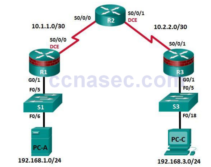
Topology
IP Addressing Table
| Device | Interface | IP Address | Subnet Mask | Default Gateway | Switch Port |
|---|---|---|---|---|---|
| R1 | G0/1 | 192.168.1.1 | 255.255.255.0 | N/A | S1 F0/5 |
| S0/0/0 (DCE) | 10.1.1.1 | 255.255.255.252 | N/A | N/A | |
| R2 | S0/0/0 | 10.1.1.2 | 255.255.255.252 | N/A | N/A |
| S0/0/1 (DCE) | 10.2.2.2 | 255.255.255.252 | N/A | N/A | |
| R3 | G0/1 | 192.168.3.1 | 255.255.255.0 | N/A | S3 F0/5 |
| S0/0/1 | 10.2.2.1 | 255.255.255.252 | N/A | N/A | |
| PC-A | NIC | 192.168.1.3 | 255.255.255.0 | 192.168.1.1 | S1 F0/6 |
| PC-C | NIC | 192.168.3.3 | 255.255.255.0 | 192.168.3.1 | S3 F0/18 |
Objectives
Part 1: Configure Basic Router Settings
♦ Configure hostname, interface IP addresses, and access passwords.
♦ Configure the static routing.
Part 2: Use CLI to Configure an IOS IPS
♦ Configure IOS IPS using CLI.
♦ Modify IPS signatures.
♦ Examine the resulting IPS configuration.
♦ Verify IPS functionality.
♦ Log IPS messages to a syslog server.
Part 3: Simulate an Attack
♦ Use a scanning tool to simulate an attack.
Background/Scenario
In this lab, you will configure the Cisco IOS IPS, which is part of the Cisco IOS Firewall feature set. IPS examines certain attack patterns and alerts or mitigates when those patterns occur. IPS alone is not enough to make a router into a secure Internet firewall, but when added to other security features, it can be a powerful defense.
You will configure IPS using the Cisco IOS CLI and then test IPS functionality. You will load the IPS Signature package from a TFTP server and configure the public crypto key using the Cisco IOS.
Note: The router commands and output in this lab are from a Cisco 1941 router with Cisco IOS Release 15.4(3)M2. Other routers and Cisco IOS versions can be used. See the Router Interface Summary Table at the end of the lab to determine which interface identifiers to use based on the equipment in the lab. The commands available and output produced are determined by the router model and Cisco IOS version used. Therefore, they might vary from what is shown in this lab.
Note: Ensure that the routers and switches have been erased and have no startup configurations.
Instructor Note: Instructions for initializing the network devices are provided in Lab 0.0.0.0.
Required Resources
- 3 routers (Cisco 1941 with Cisco IOS Release 15.4(3)M2)
- 2 switches (Cisco 2960 or comparable)
- 2 PCs (Windows Vista or Windows 7, Tftpd32 server, Nmap/Zenmap, the latest version of Java, Internet Explorer, and Flash Player)
- Serial and Ethernet cables as shown in the topology
- Console cables to configure Cisco networking devices
- IPS Signature package and public crypto key files on PC-A and PC-C (provided by the instructor)
Instructor Notes:
Router Resource Requirements:
Note: The following requirements are critical to successful completion of this lab.
- The routers that run IPS require a minimum of 192 MB DRAM and at least 2 MB free flash memory. They must also be running Cisco IOS Release 15.4(3)M2 or later to support the version 5.x format signature package.
- These requirements are critical to successful completion of this lab.
- This lab uses the newest version 5.x IPS signature file: IOS-S855-CLI.pkg. You can find this file at the CCNAS Academy Resources page on the Cisco Networking Academy website.
- This lab uses the public key encryption file: realm-cisco.pub.key. You can find this file at the CCNAS Academy Resources page on the Cisco Networking Academy website.
- The IOS-Sxxx-CLI.pkg link can be used to download the latest IPS v5.x signature package. You will need a valid CCO (Cisco.com) login username and password and a current Cisco Service Contract.
Note: It is recommended to use the latest signature file available in a production environment. However, if the amount of router flash memory is an issue in the lab environment, consider downloading an older version 5.x signature file, which requires less memory. The S364 file used in previous versions of this lab should work on older routers. Consult CCO to determine the latest version for use in a production environment.
PC-C Java Requirements
- The latest JRE for Windows Vista or Windows 7 can be downloaded from Oracle Corporation at http://www.oracle.com/.
- Refer to Part 3 for instructions on how to set the runtime parameter and Java settings.
Lab Delivery
- This lab is divided into three parts. Each part may be administered individually or in combination with others as time permits. The main goal is to configure IOS IPS on a router.
- R1 and R3 are on separate networks and communicate through R2, which simulates an ISP. The routers in this lab are configured with static routes.
- Students can work in teams of two for router configuration. One person can configure R1 and PC-A, and the other person can duplicate the configurations on R3 and PC-C.
- Although switches are shown in the topology, students can omit the switches and use straight through cables between the PCs and routers R1 and R3 instead.
Part 1: Configure Basic Router Settings
In Part 1, you will set up the network topology and configure basic settings, such as hostnames, interface IP addresses, static routing, device access, and passwords.
Note: Perform the steps listed in Part 1 on all three routers. Only R1 is shown below.
Step 1: Cable the network as shown in the topology.
Attach the devices, as shown in the topology diagram, and cable as necessary.
Step 2: Configure the basic settings for each router.
a. Configure the hostnames, as shown in the topology.
b. Configure the interface IP addresses, as shown in the IP Addressing table.
c. Configure a clock rate for serial router interfaces with a DCE serial cable attached.
R1(config)# interface S0/0/0
R1(config-if)# clock rate 64000
d. Disable DNS lookup to prevent the router from attempting to translate incorrectly entered commands.
R1(config)# no ip domain-lookup
Step 3: Configure static routing on the routers.
a. Configure a static default route using a next-hop IPv4 address from R1 to R2 and from R3 to R2.
b. Configure a static route from R2 to the R1 LAN (192.168.1.0) and from R2 to the R3 LAN (192.168.3.0)using the appropriate next-hop IPv4 address.
Step 4: Configure PC host IP settings.
Configure a static IP address, subnet mask, and default gateway for PC-A and PC-C, as shown in the IP Addressing table.
Step 5: Verify basic network connectivity.
a. Ping from R1 to R3.
If the pings are unsuccessful, troubleshoot the basic device configurations before continuing.
b. Ping from PC-A on the R1 LAN to PC-C on the R3 LAN.
If the pings are unsuccessful, troubleshoot the basic device configurations before continuing.
Note: If you can ping from PC-A to PC-C, you have demonstrated that the static routing protocol is configured and functioning correctly. If you cannot ping, but the device interfaces are up and IP addresses are correct, use the show run and show ip route commands to identify routing protocol-related problems.
Step 6: Configure a user account, encrypted passwords, and crypto keys for SSH.
Note: Passwords in this task are set to a minimum of 10 characters but are relatively simple for the benefit of performing the lab. More complex passwords are recommended in a production network.
a. Configure a minimum password length using the security passwords command to set a minimum password length of 10 characters.
R1(config)# security passwords min-length 10
b. Configure a domain name.
R1(config)# ip domain-name ccnasecurity.com
c. Configure crypto keys for SSH
R1(config)# crypto key generate rsa general-keys modulus 1024
d. Configure an admin01 user account using algorithm-type scrypt for encryption and a password of cisco12345.
R1(config)# username admin01 algorithm-type scrypt secret cisco12345
e. Configure line console 0 to use the local user database for logins. For additional security, the exectimeout command causes the line to log out after five minutes of inactivity. The logging synchronous command prevents console messages from interrupting command entry.
Note: To avoid repetitive logins during this lab, the exec-timeout command can be set to 0 0, which prevents it from expiring. However, this is not considered a good security practice.
R1(config)# line console 0
R1(config-line)# login local
R1(config-line)# exec-timeout 5 0
R1(config-line)# logging synchronous
f. Configure line aux 0 to use the local user database for logins .
R1(config)# line aux 0
R1(config-line)# login local
R1(config-line)# exec-timeout 5 0
g. Configure line vty 0 4 to use the local user database for logins and restrict access to only SSH connections.
R1(config)# line vty 0 4
R1(config-line)# login local
R1(config-line)# transport input ssh
R1(config-line)# exec-timeout 5 0
h. Configure the enable password with strong encryption.
R1(config)# enable algorithm-type scrypt secret class12345
Step 7: Save the basic configurations for all three routers.
Save the running configuration to the startup configuration from the privileged EXEC mode prompt.
R1# copy running-config startup-config
Part 2: Configuring IPS Using the Cisco IOS CLI
In Part 2 of this lab, you will configure IPS on R1 using the Cisco IOS CLI. You then review and test the resulting configuration.
Task 1: Verify Access to the R1 LAN from R2
In this task, you will verify that without IPS configured, the external R2 can ping the R1 S0/0/0 interface and PC-A on the R1 internal LAN.
Step 1: Ping from R2 to R1.
From R2, ping R1 interface S0/0/0 at IP address 10.1.1.1.
R2# ping 10.1.1.1
If the pings are unsuccessful, troubleshoot the basic device configurations before continuing.
Step 2: Ping from R2 to PC-A on the R1 LAN.
From R2, ping PC-A on the R1 LAN at IP address 192.168.1.3.
R2# ping 192.168.1.3
If the pings are unsuccessful, troubleshoot the basic device configurations before continuing.
Step 3: Display the R1 running configuration prior to configuring IPS.
Issue the show run command to review the current basic configuration on R1.
Are there any security commands related to IPS?
____________________________________________________________________________________ ___
_______________________________________________________________________________________
____________________________________________________________________________________ ___
No. There is a minimum password length of 10. Login passwords and exec-timeout are defined on the console, vty, and aux lines.
Task 2: Prepare the Router and TFTP Server
Step 1: Verify the availability of Cisco IOS IPS files.
To configure Cisco IOS IPS 5.x, the IOS IPS Signature package file and public crypto key file must be available on PC-A. Check with your instructor if these files are not on the PC. These files can be downloaded from www.cisco.com with a valid user account that has proper authorization.
a. Verify that the IOS-Sxxx-CLI.pkg file is in a TFTP folder. This is the signature package. The xxx is the version number and varies depending on which file was downloaded.
b. Verify that the realm-cisco.pub.key.txt file is available and note its location on PC-A. This is the public crypto key used by IOS IPS.
Step 2: Verify or create the IPS directory in router flash on R1.
a. In this step, you will verify the existence of, or create a directory in, the router flash memory where the required signature files and configurations will be stored.
Note: Alternatively, you can use a USB flash drive connected to the router USB port to store the signature files and configurations. The USB flash drive must remain connected to the router USB port if it is used as the IOS IPS configuration directory location. IOS IPS also supports any Cisco IOS file system as its configuration location with proper write access.
b. From the R1 CLI, display the contents of flash memory using the show flash command and check for the ipsdir directory.
R1# show flash
c. If the ipsdir directory is not listed, create it in privileged EXEC mode.
R1# mkdir ipsdir
Create directory filename [ipsdir]? <Enter>
Created dir flash:ipsdir
d. If the directory already exists, the following message displays :
%Error Creating dir flash:ipsdir (Can't create a file that exists)
Use the delete command to erase the content of ipsdir directory.
R1# delete flash:ipsdir/*
Delete filename [/ipsdir/*]?
Delete flash:/ipsdir/R1-sigdef-default.xml? [confirm]
Delete flash:/ipsdir/R1-sigdef-delta.xml? [confirm]
Delete flash:/ipsdir/R1-sigdef-typedef.xml? [confirm]
Delete flash:/ipsdir/R1-sigdef-category.xml? [confirm]
Delete flash:/ipsdir/R1-seap-delta.xml? [confirm]
Delete flash:/ipsdir/R1-seap-typedef.xml? [confirm]
Note: Use this command with caution. If there are no files in the ipsdir directory, the following message displays:
R1# delete flash:ipsdir/*
Delete filename [/ipsdir/*]?
No such file
e. From the R1 CLI, verify that the directory is present using the dir flash: or dir flash:ipsdir command.
R1# dir flash:
Directory of flash:/

1 -rw- 75551300 Feb 16 2015 01:53:10 +00:00 c1900-univeralk9-mz.SPA.154-3.M2.bin
2 drw- 0 Mar 8 2015 12:38:14 +00:00 ipsdir
or
R1# dir flash:ipsdir

Directory of flash:/ipsdir/
No files in directory
Note: The directory exists, but there are currently no files in it.
Task 3: Configure the IPS Crypto Key
The crypto key verifies the digital signature for the master signature file (sigdef-default.xml). The contents are signed by a Cisco private key to guarantee the authenticity and integrity at every release.
Step 1: Copy and paste the crypto key file into R1.
In global configuration mode, select and copy the crypto key file named realm-cisco.pub.key.txt.
crypto key pubkey-chain rsa
 named-key realm-cisco.pub signature
  key-string
   30820122 300D0609 2A864886 F70D0101 01050003 82010F00 3082010A 02820101
   00C19E93 A8AF124A D6CC7A24 5097A975 206BE3A2 06FBA13F 6F12CB5B 4E441F16
   17E630D5 C02AC252 912BE27F 37FDD9C8 11FC7AF7 DCDD81D9 43CDABC3 6007D128
   B199ABCB D34ED0F9 085FADC1 359C189E F30AF10A C0EFB624 7E0764BF 3E53053E
   5B2146A9 D7A5EDE3 0298AF03 DED7A5B8 9479039D 20F30663 9AC64B93 C0112A35
   FE3F0C87 89BCB7BB 994AE74C FA9E481D F65875D6 85EAF974 6D9CC8E3 F0B08B85
   50437722 FFBE85B9 5E4189FF CC189CB9 69C46F9C A84DFBA5 7A0AF99E AD768C36
   006CF498 079F88F8 A3B3FB1F 9FB7B3CB 5539E1D1 9693CCBB 551F78D2 892356AE
   2F56D826 8918EF3C 80CA4F4D 87BFCA3B BFF668E9 689782A5 CF31CB6E B4B094D3
   F3020301 0001
  quit
Step 2: Apply the contents of the text file to the router.
a. At the R1 privileged EXEC mode prompt, enter global configuration mode using the config t command.
b. Paste the copied crypto key content at the global configuration mode prompt.
R1(config)#
R1(config)# crypto key pubkey-chain rsa
R1(config-pubkey-chain)# named-key realm-cisco.pub signature
R1(config-pubkey-key)# key-string
Enter a public key as a hexidecimal number ....

R1(config-pubkey)#$2A864886 F70D0101 01050003 82010F00 3082010A 02820101
R1(config-pubkey)#$D6CC7A24 5097A975 206BE3A2 06FBA13F 6F12CB5B 4E441F16
R1(config-pubkey)#$912BE27F 37FDD9C8 11FC7AF7 DCDD81D9 43CDABC3 6007D128
R1(config-pubkey)#$085FADC1 359C189E F30AF10A C0EFB624 7E0764BF 3E53053E
R1(config-pubkey)#$0298AF03 DED7A5B8 9479039D 20F30663 9AC64B93 C0112A35
R1(config-pubkey)#$994AE74C FA9E481D F65875D6 85EAF974 6D9CC8E3 F0B08B85
R1(config-pubkey)#$5E4189FF CC189CB9 69C46F9C A84DFBA5 7A0AF99E AD768C36
R1(config-pubkey)#$A3B3FB1F 9FB7B3CB 5539E1D1 9693CCBB 551F78D2 892356AE
R1(config-pubkey)#$80CA4F4D 87BFCA3B BFF668E9 689782A5 CF31CB6E B4B094D3
R1(config-pubkey)# F3020301 0001
R1(config-pubkey)# quit
R1(config-pubkey-key)#
c. Exit global configuration mode and issue the show run command to confirm that the crypto key is configured.
Task 4: Configure IPS
Step 1: Create an IPS rule.
a. On R1, create an IPS rule name using the ip ips name name command in global configuration mode. Name the IPS rule iosips. This will be used later on an interface to enable IPS.
R1(config)# ip ips name iosips
b. You can specify an optional extended or standard access control list (ACL) to filter the traffic that will be scanned by this rule name. All traffic permitted by the ACL is subject to inspection by the IPS. Traffic that is denied by the ACL is not inspected by the IPS.
c. To see the options available for specifying an ACL with the rule name, use the ip ips name command and the CLI help function (?).
R1(config)# ip ips name ips list ?
  <1-199> Numbered access list
  WORD Named access list
Step 2: Configure the IPS Signature storage location in router flash memory.
The IPS files will be stored in the ipsdir directory that was created in Task 2, Step 2. Configure the location using the ip ips config location command.
R1(config)# ip ips config location flash:ipsdir
Step 3: Enable IPS SDEE event notification.
The Cisco Security Device Event Exchange (SDEE) server is a Simple Object Access Protocol (SOAP) based, IDS alert format and transport protocol specification. SDEE replaces Cisco RDEP.
To use SDEE, the HTTP server must be enabled with the ip http server command. If the HTTP server is not enabled, the router cannot respond to the SDEE clients because it cannot see the requests. SDEE notification is disabled by default, and must be explicitly enabled.
R1(config)# ip http server
To enable SDEE, use the following command:
R1(config)# ip ips notify sdee
Step 4: Enable IPS syslog support.
IOS IPS also supports the use of syslog to send event notifications. SDEE and syslog can be used independently or enabled at the same time to send IOS IPS event notification. Syslog notification is enabled by default.
a. If console logging is enabled, IPS syslog messages display. Enable syslog if it is not enabled.
R1(config)# ip ips notify log
b. Use the show clock command to verify the current time and date for the router. Use the clock set command in privileged EXEC mode to reset the clock if necessary. The following example shows how to set the clock.
R1# clock set 01:20:00 8 march 2015
c. Verify that the timestamp service for logging is enabled on the router using the show run command. Enable the timestamp service if it is not enabled.
R1(config)# service timestamps log datetime msec
d. To send log messages to the syslog server on PC-A, use the following command:
R1(config)# logging 192.168.1.3
e. To see the type and level of logging enabled on R1, use the show logging command.
R1# show logging
Note: Verify that you have connectivity between R1 and PC-A by pinging from PC-A to the R1 Fa0/1 interface IP address 192.168.1.1. If it is not successful, troubleshoot as necessary before continuing.
The next step describes how to download one of the freeware syslog servers if one is unavailable on PC-A.
Step 5: (Optional) Download and start the syslog server.
If a syslog server is not currently available on PC-A, you can download the Tftpd32 from http://tftpd32.jounin.net/. If the syslog server is available on the PC, go to Step 6.
Start the syslog server software on PC-A to send log messages to it.
Step 6: Configure IOS IPS to use one of the pre-defined signature categories.
IOS IPS with Cisco 5.x format signatures operates with signature categories, just like Cisco IPS appliances do. All signatures are pre-grouped into categories, and the categories are hierarchical. This helps classify signatures for easy grouping and tuning.
Warning: The “all” signature category contains all signatures in a signature release. Do not unretired the “all” category because IOS IPS cannot compile and use all the signatures contained in a signature release at one time. The router will run out of memory.
Note: When configuring IOS IPS, it is required to first retire all the signatures in the “all” category and then unretire selected signature categories.
Instructor Note: The order in which the signature categories are configured on the router is also important. IOS IPS processes the category commands in the order listed in the configuration. Some signatures belong to multiple categories. If multiple categories are configured and a signature belongs to more than one of them, IOS IPS uses the signature properties (for example, retired/unretired, actions, etc.) in the last configured category.
In the following example, all signatures in the all category are retired, and then the ios_ips basic category is unretired.
R1(config)# ip ips signature-category
R1(config-ips-category)# category all
R1(config-ips-category-action)# retired true
R1(config-ips-category-action)# exit
R1(config-ips-category)# category ios_ips basic
R1(config-ips-category-action)# retired false
R1(config-ips-category-action)# exit
R1(config-ips-category)# exit
Do you want to accept these changes? [confirm] <Enter>

Jan 6 01:32:37.983: Applying Category configuration to signatures ...
Step 7: Apply the IPS rule to an interface.
a. Apply the IPS rule to an interface with the ip ips name direction command in interface configuration mode. Apply the rule you just created for inbound traffic on the S0/0/0 interface. After you enable IPS,some log messages will be sent to the console line, which indicates that the IPS engines are being initialized.
Note: The direction in means that IPS inspects only traffic going into the interface. Similarly, out means only traffic going out the interface. To enable IPS to inspect both in and out traffic, enter the IPS rule name for in and out separately on the same interface.
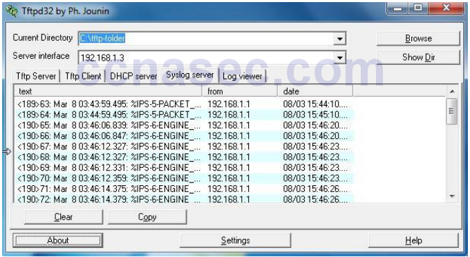
R1(config)# interface serial0/0/0
R1(config-if)# ip ips iosips in

Jan 6 03:03:30.495: %IPS-6-ENGINE_BUILDS_STARTED: 03:03:30 UTC Jan 6 2008
Jan 6 03:03:30.495: %IPS-6-ENGINE_BUILDING: atomic-ip - 3 signatures - 1 of 13 engines
Jan 6 03:03:30.511: %IPS-6-ENGINE_READY: atomic-ip - build time 16 ms – packets for this engine will be scanned
Jan 6 03:03:30.511: %IPS-6-ALL_ENGINE_BUILDS_COMPLETE: elapsed time 16 ms
The message also displays on the syslog server if it is enabled. The Tftpd32 syslog server is shown here.
Note: The following message may display if the router does not have a built-in IOS signature file.
*******************************************************************
The signature package is missing or was saved by a previous version
IPS Please load a new signature package
*******************************************************************
Jan 6 01:22:17.383: %IPS-3-SIG_UPDATE_REQUIRED: IOS IPS requires a signature update
package to be loaded
b. Although the R1 Fa0/1 interface is an internal interface, configure it with IPS to respond to internal attacks. Apply the IPS rule to the R1 Fa0/1 interface in the inbound direction.
R1(config)# interface g0/1
R1(config-if)# ip ips iosips in
Step 8: Save the running configuration.
Enter privileged EXEC mode and save the running configuration to the startup-config file.
R1# copy run start
Task 5: Load the IOS IPS Signature Package to the Router
The most common way to load the signature package to the router is to use TFTP. Refer to Step 4 for alternative methods of loading the IOS IPS signature package. The alternative methods include the use of FTP and a USB flash drive.
Step 1: (Optional) Download the TFTP server.
The Tftpd32 freeware TFTP server is used in this task. Many other free TFTP servers are also available. If a TFTP server is currently unavailable on PC-A, you can download the latest version of Tftpd32 from http://tftpd32.jounin.net/. If it is already installed, go to Step 2.
Note: This lab uses the Tftpd32 TFTP server. This software also includes a syslog server, which runs simultaneously with the TFTP server.
Step 2: Start the TFTP server on PC-A and verify the IPS file directory.
a. Verify connectivity between R1 and PC-A and the TFTP server using the ping command.
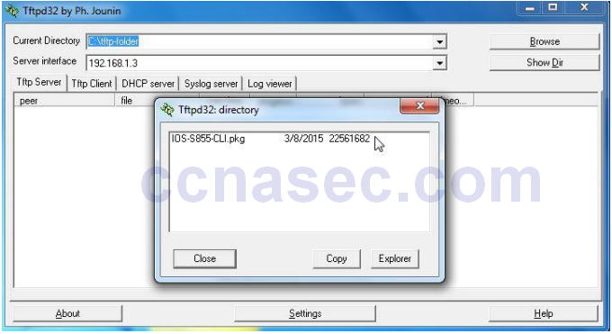
b. Verify that the PC has the IPS Signature package file in a directory on the TFTP server. This file is typically named IOS-Sxxx-CLI.pkg, where xxx is the signature file version.
Note: If this file is not present, contact your instructor before continuing.
c. Start Tftpd32 or another TFTP server and set the server interface to PC-A’s network interface (192.168.1.3), and set the default directory to the one with the IPS Signature package in it. The Tftpd32 screen is shown below with the C:\tftp-folder\ directory contents displayed. Take note of the filename for use in the next step.
Note: It is recommended to use the latest signature file available in a production environment. However, if the amount of router flash memory is an issue in a lab environment, you may use an older version 5.x signature, which requires less memory. The S364 file is used with this lab for demonstration purposes, although newer versions are available. Consult CCO to determine the latest version.
Step 3: Copy the signature package from the TFTP server to the router.
If you do not have a TFTP server available, and you are using a router with a USB port, go to Step 5 and use the procedure described there.
a. Use the copy tftp command to retrieve the signature file and load it into the Intrusion Detection Configuration. Use the idconf keyword at the end of the copy command.
Note: Signature compiling begins immediately after the signature package is loaded to the router. You can see the messages on the router with logging level 6 or above enabled.
# copy tftp://192.168.1.3/IOS-S855-CLI.pkg idconf
Loading IOS-S855-CLI.pkg from 192.168.1.3 (via GigabitEthernet0/1): !!!!!OO!!
Mar 8 03:43:59.495: %IPS-5-PACKET_UNSCANNED: atomic-ip - fail open - packets
passed
unscanned!!!!!!!!!!!!!!!!!!!!!!!!!!!!!!!!!!!!!!!!!!!!!!!!!!!!!!!!!!!!!!!!!!
Mar 8 03:44:59.495: %IPS-5-PACKET_UNSCANNED: atomic-ip - fail open - packets
passed unscanned!!!!!!!!!!!!!!!!
[OK - 22561682 bytes]

Mar 8 03:46:06.839: %IPS-6-ENGINE_BUILDS_STARTED: 03:46:06 UTC Mar 8 2015
Mar 8 03:46:06.847: %IPS-6-ENGINE_BUILDING: atomic-ip - 539 signatures - 1
of 13 engines
Mar 8 03:46:12.327: %IPS-6-ENGINE_READY: atomic-ip - build time 5480 ms -packets for this engine will be scanned
Mar 8 03:46:12.327: %IPS-6-ENGINE_BUILDING: normalizer - 10 signatures - 2
of 13 engines
Mar 8 03:46:12.331: %IPS-6-ENGINE_READY: normalizer - build time 4 ms -packets for this engine will be scanned
Mar 8 03:46:12.359: %IPS-6-ENGINE_BUILDING: service-http - 1837 signatures -3 of 13 engines
Mar 8 03:46:14.375: %IPS-6-ENGINE_READY: service-http - build time 2016 ms -packets for this engine will be scanned
Mar 8 03:46:14.379: %IPS-6-ENGINE_BUILDING: service-smb-advanced - 76
signatures - 4 of 13 engines
Mar 8 03:46:15.003: %IPS-6-ENGINE_READY: service-smb-advanced - build time
624 ms - packets for this engine will be scanned
Mar 8 03:46:15.003: %IPS-6-ENGINE_BUILDING: service-msrpc - 37 signatures -5 of 13 engines
Mar 8 03:46:15.107: %IPS-6-ENGINE_READY: service-msrpc - build time 104 ms -packets for this engine will be scanned
Mar 8 03:46:15.111: %IPS-6-ENGINE_BUILDING: state - 39 signatures - 6 of 13
engines
Mar 8 03:46:15.203: %IPS-6-ENGINE_READY: state - build time 92 ms - packets
for this engine will be scanned
Mar 8 03:46:15.203: %IPS-6-ENGINE_BUILDING: service-ftp - 3 signatures - 7
of 13 engines
Mar 8 03:46:15.207: %IPS-6-ENGINE_READY: service-ftp - build time 4 ms -packets for this engine will be scanned
Mar 8 03:46:15.271: %IPS-6-ENGINE_BUILDING: string-tcp - 3782 signatures - 8
of 13 engines
Mar 8 03:46:19.887: %IPS-6-ENGINE_READY: string-tcp - build time 4616 ms -packets for this engine will be scanned
Mar 8 03:46:19.895: %IPS-6-ENGINE_BUILDING: service-rpc - 79 signatures - 9
of 13 engines
Mar 8 03:46:19.991: %IPS-6-ENGINE_READY: service-rpc - build time 96 ms -packets for this engine will be scanned
Mar 8 03:46:19.991: %IPS-6-ENGINE_BUILDING: service-dns - 39 signatures - 10
of 13 engines
Mar 8 03:46:20.027: %IPS-6-ENGINE_READY: service-dns - build time 36 ms -packets for this
R1#
R1# engine will be scanned
Mar 8 03:46:20.027: %IPS-6-ENGINE_BUILDING: string-udp - 80 signatures - 11
of 13 engines
Mar 8 03:46:20.087: %IPS-6-ENGINE_READY: string-udp - build time 60 ms -packets for this engine will be scanned
Mar 8 03:46:20.099: %IPS-6-ENGINE_BUILDING: multi-string - 614 signatures -12 of 13 engines
Mar 8 03:46:20.803: %IPS-6-ENGINE_READY: multi-string - build time 700 ms -packets for this engine will be scanned
Mar 8 03:46:20.803: %IPS-6-ENGINE_BUILDING: string-icmp - 3 signa
R1#tures - 13 of 13 engines
Mar 8 03:46:20.803: %IPS-6-ENGINE_READY: string-icmp - build time 0 ms -packets for this engine will be scanned
Mar 8 03:46:20.803: %IPS-6-ALL_ENGINE_BUILDS_COMPLETE: elapsed time 13964 ms
b. Use the dir flash command to see the contents of the ipsdir directory created earlier. There should be six files, as shown here.
R1# dir flash:ipsdir
Directory of flash0:/ipsdir/

4   -rw-      255 Mar 8 2015 02:45:40 +00:00 iosips-sig-delta.xmz
5   -rw-    16625 Mar 8 2015 03:43:52 +00:00 iosips-sig-typedef.xmz
6   -rw-   143832 Mar 8 2015 03:43:58 +00:00 iosips-sig-category.xmz
7   -rw-      304 Mar 8 2015 02:45:42 +00:00 iosips-seap-delta.xmz
8   -rw-      835 Mar 8 2015 02:45:42 +00:00 iosips-seap-typedef.xmz
9   -rw-  1632555 Mar 8 2015 03:45:18 +00:00 iosips-sig-default.xmz
Step 4: Verify that the signature package is properly compiled.
a. Use the show ip ips signature count command to see the counts for the signature package compiled.
R1# show ip ips signature count

Cisco SDF release version S364.0
Trend SDF release version V0.0

Signature Micro-Engine: multi-string: Total Signatures 11
    multi-string enabled signatures: 9
    multi-string retired signatures: 11

Signature Micro-Engine: service-http: Total Signatures 662
    service-http enabled signatures: 163
    service-http retired signatures: 565
    service-http compiled signatures: 97
    service-http obsoleted signatures: 1

Signature Micro-Engine: string-tcp: Total Signatures 1148
    string-tcp enabled signatures: 622
    string-tcp retired signatures: 1031
    string-tcp compiled signatures: 117
    string-tcp obsoleted signatures: 21

<Output Omitted>

Total Signatures: 2435
    Total Enabled Signatures: 1063
    Total Retired Signatures: 2097
    Total Compiled Signatures: 338
    Total Obsoleted Signatures: 25
Note: If you see an error message during signature compilation, such as “%IPS-3-INVALID_DIGITAL_SIGNATURE: Invalid Digital Signature found (key not found),” it means the public crypto key is invalid. Refer to Task 3, Configure the IPS Crypto Key, to reconfigure the public crypto key.
b. Use the show ip ips all command to view the IPS configuration status summary. To which interfaces and in which direction is the iosips rule applied?
____________________________________________________________________________________
____________________________________________________________________________________
S0/0/0 inbound and Fa0/1 inbound.
R1# show ip ips all

IPS Signature File Configuration Status
    Configured Config Locations: flash:ipsdir/
    Last signature default load time: 18:47:52 UTC Jan 6 2009
    Last signature delta load time: 20:11:35 UTC Jan 6 2009
    Last event action (SEAP) load time: -none

    General SEAP Config:
    Global Deny Timeout: 3600 seconds
    Global Overrides Status: Enabled
    Global Filters Status: Enabled

IPS Auto Update is not currently configured

IPS Syslog and SDEE Notification Status
    Event notification through syslog is enabled
    Event notification through SDEE is enabled

IPS Signature Status
    Total Active Signatures: 339
    Total Inactive Signatures: 2096

IPS Packet Scanning and Interface Status
    IPS Rule Configuration
      IPS name iosips
    IPS fail closed is disabled
    IPS deny-action ips-interface is false
    Interface Configuration
     Interface Serial0/0/0
      Inbound IPS rule is iosips
      Outgoing IPS rule is not set
    Interface FastEthernet0/1
      Inbound IPS rule is iosips
      Outgoing IPS rule is not set

IPS Category CLI Configuration:
    Category all:
      Retire: True
    Category ios_ips basic:
      Retire: False
Step 5: (Optional) Alternative methods of copying the signature package to the router.
If you used TFTP to copy the file and will not use one of these alternative methods, read through the procedures described here to become familiar with them. If you use one of these methods instead of TFTP, return to Step 4 to verify that the signature package loaded properly.
FTP method: Although the TFTP method is generally adequate, the signature file is rather large and FTP can provide another method of copying the file. You can use an FTP server to copy the signature file to the router with this command:
copy ftp://<ftp_user:password@Server_IP_address>/<signature_package> idconf
In the following example, the user admin must be defined on the FTP server with a password of cisco.
R1# copy ftp://admin:[email protected]/IOS-S855-CLI.pkg idconf
Loading IOS-S855-CLI.pkg !!!!!!!!!!!!!!!!!!!!!!!!!!!!!!
[OK - 7608873/4096 bytes]
USB method: If there is no access to an FTP or a TFTP server, you can use a USB flash drive to load the signature package to the router.
a. Copy the signature package onto the USB drive.
b. Connect the USB drive to one of the USB ports on the router.
c. Use the show file systems command to see the name of the USB drive. In the following output, a 4 GB USB drive is connected to the USB port on the router as file system usbflash0:
R1# show file systems
File Systems:

Size(b)         Free(b)      Type     Flags       Prefixes
      -               -    opaque       rw        archive:
      -               -    opaque       rw        system:
      -               -    opaque       rw        tmpsys:
      -               -    opaque       rw        null:
      -               -   network       rw        tftp:
 196600          185972     nvram       rw        nvram:
* 64012288     14811136      disk       rw        flash:#
      -               -    opaque       wo        syslog:
      -               -    opaque       rw        xmodem:
      -               -    opaque       rw        ymodem:
      -               -   network       rw        rcp:
      -               -   network       rw        pram:
      -               -   network       rw        http:
      -               -   network       rw        ftp:
      -               -   network       rw        scp:
      -               -    opaque       ro        tar:
      -               -   network       rw        https:
      -               -    opaque       ro        cns:
4001378304   3807461376  usbflash       rw        usbflash0:
d. Verify the contents of the flash drive using the dir command.
R1# dir usbflash0:
Directory of usbflash0:/
1 -rw- 807 Mar 8 2015 13:20:12 +00:00 realm-cisco.pub.key
2 -rw- 22561682 Mar 8 2015 09:57:38 +00:00 IOS-S855-CLI.pkg
e. Use the copy command with the idconf keyword to copy the signature package to the router.
R1# copy usbflash0:IOS-S855-CLI.pkg idconf
The USB copy process can take 60 seconds or more, and no progress indicator displays. When the copyprocess is complete, numerous engine building messages display. These must finish before thecommand prompt returns.
Task 6: Test the IPS Rule and Modify a Signature
You can work with signatures in many ways. They can be retired and unretired, enabled and disabled, andtheir characteristics and actions can be changed. In this task, you first test the default behavior of IOS IPS bypinging it from the outside.
Step 1: Ping from R2 to the R1 serial 0/0/0 interface.
From the CLI on R2, ping R1 S0/0/0 at IP address 10.1.1.1. The pings are successful because the ICMP
Echo Request signature 2004:0 is retired.
Step 2: Ping from R2 to PC-A.
From the CLI on R2, ping PC-A at IP address 192.168.1.3. These pings are also successful because of the retired signature. This is the default behavior of the IPS signatures.
R2# ping 192.168.1.3

Type escape sequence to abort.
Sending 5, 100-byte ICMP Echos to 192.168.1.3, timeout is 2 seconds:
!!!!!
Success rate is 100 percent (5/5), round-trip min/avg/max = 1/1/4 ms
Step 3: Modify the signature.
You can use the Cisco IOS CLI to change signature status and actions for one signature or a group of signatures based on signature categories.
The following example shows how to unretire the echo request signature, enable it, change the signature action to alert, and drop and reset for signature 2004 with a subsig ID of 0.
R1(config)# ip ips signature-definition
R1(config-sigdef)# signature 2004 0
R1(config-sigdef-sig)#status
R1(config-sigdef-sig-status)# retired false
R1(config-sigdef-sig-status)# enabled true
R1(config-sigdef-sig-status)# engine
R1(config-sigdef-sig-engine)# event-action produce-alert
R1(config-sigdef-sig-engine)# event-action deny-packet-inline
R1(config-sigdef-sig-engine)# event-action reset-tcp-connection
R1(config-sigdef-sig-engine)# exit
R1(config-sigdef-sig)# exit
R1(config-sigdef)# exit
Do you want to accept these changes? [confirm] <Enter>

Mar 8 05:37:45.775: %IPS-6-ENGINE_BUILDS_STARTED: 05:37:45 UTC Mar 8 2015
Mar 8 05:37:46.099: %IPS-6-ENGINE_BUILDING: atomic-ip - 539 signatures - 1
of 13 engines
R1(config)#
Mar 8 05:37:51.219: %IPS-6-ENGINE_READY: atomic-ip - build time 5120 ms -packets for this engine will be scanned
Mar 8 05:37:51.427: %IPS-6-ALL_ENGINE_BUILDS_COMPLETE: elapsed time 5652 ms
Step 4: Ping from R2 to R1 serial 0/0/0 interface.
a. Start the syslog server.
b. From the CLI on R2, ping R1 S0/0/0 at IP address 10.1.1.1. Were the pings successful? Explain.
____________________________________________________________________________________
____________________________________________________________________________________
No. The 2004 Echo Request signature is now unretired, enabled, and set to take action when a ping is attempted.
R2# ping 10.1.1.1

Type escape sequence to abort.
Sending 5, 100-byte ICMP Echos to 10.1.1.1, timeout is 2 seconds:
.....
Success rate is 0 percent (0/5)
Step 5: Ping from R2 to PC-A.
a. From the CLI on R2, ping PC-A at IP address 192.168.1.3. Were the pings successful? Explain.
____________________________________________________________________________________
____________________________________________________________________________________
No. The 2004 Echo Request signature is now active.
R2# ping 192.168.1.3

Type escape sequence to abort.
Sending 5, 100-byte ICMP Echos to 192.168.1.3, timeout is 2 seconds:
.....
Success rate is 0 percent (0/5)
b. Notice the IPS messages from R1 on the syslog server screen below. How many messages were generated from the R2 pings to R1 and PC-A?
____________________________________________________________________________________
____________________________________________________________________________________
10 messages, five for the ping from 10.1.1.2 to 10.1.1.1 and five for the ping to 192.168.1.3.
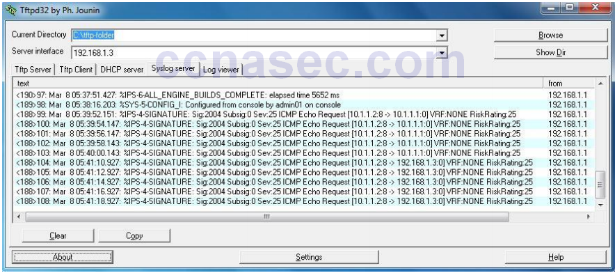
Note: The ICMP echo request IPS risk rating (severity level) is relatively low at 25. Risk rating can range from 0 to 100.
Part 3: Simulate an Attack
Task 1: Verify IPS with Zenmap
Nmap/Zenmap is a network scanning tool that allows you to discover network hosts and resources, including services, ports, operating systems, and other fingerprinting information. Zenmap is the graphical interface for Nmap. Nmap should not be used to scan networks without prior permission. The act of network scanning can be considered a form of network attack.
Nmap/Zenmap will test the IPS capabilities on R1. You will run the scanning program from PC-A and attempt to scan open ports on router R2 before and after applying IPS rule iosips on R1.
Step 1: Download and install Nmap/Zenmap.
a. If Nmap/Zenmap is not installed on PC-A, download Nmap/Zenmap at http://nmap.org/download.html.
b. Search for the appropriate binaries for your operating system.
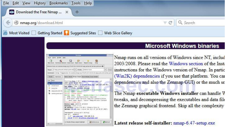
c. Install Nmap/Zenmap.
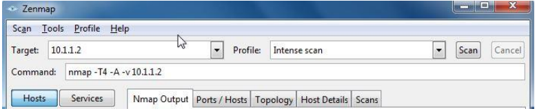
Step 2: Run Nmap/Zenmap and set scanning options.
a. Start Zenmap on PC-A.
b. Enter IP address 10.1.1.2 as the Target and verify that Intense scan is selected as the Profile. Click Scan to begin the scan.
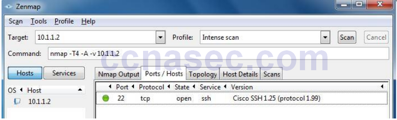
c. After the scan is complete, review the results displayed in the Nmap Output tab.
d. Click the Ports/Hosts tab. How many open ports did Nmap find on R2? What are the associated port numbers and services?
____________________________________________________________________________________
____________________________________________________________________________________
No open ports were found by Zenmap.
e. Exit Zenmap.
Task 2: Observe the syslog messages on R1.
You should see syslog entries on the R1 console and on the syslog server if it is enabled. The descriptions should include phrases, such as TCP NULL Packet and TCP SYN/FIN Packet.
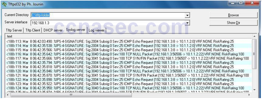
a. What is the IPS risk rating or severity level (Sev:) of the TCP NULL Packet, signature 3040?
____________________________________________________________________________________
100
b. What is the IPS risk rating or severity level (Sev:) of the TCP SYN/FIN packet, signature 3041?
____________________________________________________________________________________
100
Reflection
1. If changes are made to a signature while using version 5.x signature files, are they visible in the router running the configuration?
_______________________________________________________________________________________
_______________________________________________________________________________________
_______________________________________________________________________________________
_______________________________________________________________________________________
_______________________________________________________________________________________
_______________________________________________________________________________________
_______________________________________________________________________________________
_______________________________________________________________________________________
No. The signature files are not part of Cisco IOS or router configuration. There is no information regarding the details of the signatures or the signature file contents visible to the user, except via Cisco IOS CLI manipulation and IPS show commands.
Router Interface Summary Table
| Router Interface Summary | ||||
|---|---|---|---|---|
| Router Model | Ethernet Interface #1 | Ethernet Interface #2 | Serial Interface #1 | Serial Interface #2 |
| 1800 | Fast Ethernet 0/0 (Fa0/0) |
Fast Ethernet 0/1 (Fa0/1) |
Serial 0/0/0 (S0/0/0) | Serial 0/0/1 (S0/0/1) |
| 1900 | Gigabit Ethernet 0/0 (G0/0) |
Gigabit Ethernet 0/1 (G0/1) |
Serial 0/0/0 (S0/0/0) | Serial 0/0/1 (S0/0/1) |
| 2801 | Fast Ethernet 0/0 (Fa0/0) |
Fast Ethernet 0/1 (Fa0/1) |
Serial 0/1/0 (S0/1/0) | Serial 0/1/1 (S0/1/1) |
| 2811 | Fast Ethernet 0/0 (Fa0/0) |
Fast Ethernet 0/1 (Fa0/1) |
Serial 0/0/0 (S0/0/0) | Serial 0/0/1 (S0/0/1) |
| 2900 | Gigabit Ethernet 0/0 (G0/0) |
Gigabit Ethernet 0/1 (G0/1) |
Serial 0/0/0 (S0/0/0) | Serial 0/0/1 (S0/0/1) |
| Note: To find out how the router is configured, look at the interfaces to identify the type of router and how many interfaces the router has. There is no way to effectively list all the combinations of configurations for each router class. This table includes identifiers for the possible combinations of Ethernet and Serial interfaces in the device. The table does not include any other type of interface, even though a specific router may contain one. An example of this might be an ISDN BRI interface. The string in parenthesis is the legal abbreviation that can be used in Cisco IOS commands to represent the interface. |
||||
Router R1
R1# show run
Building configuration...

Current configuration : 2776 bytes
!
version 15.4
service timestamps debug datetime msec
service timestamps log datetime msec
no service password-encryption
!
hostname R1
!
boot-start-marker
boot-end-marker
!
security passwords min-length 10
enable secret 9 $9$jS7nkxcSkFkPMU$r1r2HMA6VSH8LBAcghcnLj.lEru/qTEX.f6ncaaCyq.
!
no aaa new-model
memory-size iomem 15
!
no ip domain lookup
ip domain name ccnasecurity.com
ip ips config location flash:ipsdir retries 1
ip ips notify SDEE
ip ips name iosips
!
ip ips signature-category
category all
retired true
category ios_ips basic
retired false
!
ip cef
no ipv6 cef
!
multilink bundle-name authenticated
!
cts logging verbose
!
username admin01 secret 9
$9$6GyiPInpJqZEAE$fCAv1VPLQFOVY1ipvHm.LqtPYDYfoj..SQLkgaONHB2
!
redundancy
!
crypto key pubkey-chain rsa
named-key realm-cisco.pub signature
key-string
30820122 300D0609 2A864886 F70D0101 01050003 82010F00 3082010A 02820101
00C19E93 A8AF124A D6CC7A24 5097A975 206BE3A2 06FBA13F 6F12CB5B 4E441F16
17E630D5 C02AC252 912BE27F 37FDD9C8 11FC7AF7 DCDD81D9 43CDABC3 6007D128
B199ABCB D34ED0F9 085FADC1 359C189E F30AF10A C0EFB624 7E0764BF 3E53053E
5B2146A9 D7A5EDE3 0298AF03 DED7A5B8 9479039D 20F30663 9AC64B93 C0112A35
FE3F0C87 89BCB7BB 994AE74C FA9E481D F65875D6 85EAF974 6D9CC8E3 F0B08B85
50437722 FFBE85B9 5E4189FF CC189CB9 69C46F9C A84DFBA5 7A0AF99E AD768C36
006CF498 079F88F8 A3B3FB1F 9FB7B3CB 5539E1D1 9693CCBB 551F78D2 892356AE
2F56D826 8918EF3C 80CA4F4D 87BFCA3B BFF668E9 689782A5 CF31CB6E B4B094D3
F3020301 0001
quit
!
interface Embedded-Service-Engine0/0
no ip address
shutdown
!
interface GigabitEthernet0/0
no ip address
shutdown
duplex auto
speed auto
!
interface GigabitEthernet0/1
ip address 192.168.1.1 255.255.255.0
ip ips iosips in
duplex auto
speed auto
!
interface Serial0/0/0
ip address 10.1.1.1 255.255.255.252
ip ips iosips in
clock rate 64000
!
interface Serial0/0/1
no ip address
shutdown
!
ip forward-protocol nd
!
ip http server
no ip http secure-server
!
ip route 0.0.0.0 0.0.0.0 10.1.1.2
!
logging host 192.168.1.3
!
control-plane
!
line con 0
exec-timeout 5 0
logging synchronous
login local
line aux 0
exec-timeout 5 0
login local
line 2
no activation-character
no exec
transport preferred none
transport output pad telnet rlogin lapb-ta mop udptn v120 ssh
stopbits 1
line vty 0 4
exec-timeout 5 0
login local
transport input ssh
!
scheduler allocate 20000 1000
!
end
Router R2
R2# show run
Building configuration...

Current configuration : 1725 bytes
!
version 15.4
service timestamps debug datetime msec
service timestamps log datetime msec
no service password-encryption
!
hostname R2
!
boot-start-marker
boot-end-marker
!
security passwords min-length 10
enable secret 9 $9$gOx1nSSUWDg7dk$mkhWUmZ9aNM7hsMfn2K2JNIvtdjDJiRv4dy4e3pbpBQ
!
no aaa new-model
memory-size iomem 15
!
no ip domain lookup
ip domain name ccnasecurity.com
ip cef
no ipv6 cef
!
multilink bundle-name authenticated
!
cts logging verbose
!
username admin01 secret 9
$9$ATnhIZ7o5Gngf.$wsm64pYOF.UD9dclr7mjVollS6OpuORlXltHAppCxeE
!
redundancy
!
interface Embedded-Service-Engine0/0
no ip address
shutdown
!
interface GigabitEthernet0/0
no ip address
shutdown
duplex auto
speed auto
!
interface GigabitEthernet0/1
no ip address
shutdown
duplex auto
speed auto
!
interface Serial0/0/0
ip address 10.1.1.2 255.255.255.252
!
interface Serial0/0/1
ip address 10.2.2.2 255.255.255.252
clock rate 64000
!
ip forward-protocol nd
!
no ip http server
no ip http secure-server
!
ip route 192.168.1.0 255.255.255.0 10.1.1.1
ip route 192.168.3.0 255.255.255.0 10.2.2.1
!
control-plane
!
line con 0
exec-timeout 0 0
logging synchronous
login local
line aux 0
exec-timeout 5 0
login local
line 2
no activation-character
no exec
transport preferred none
transport output pad telnet rlogin lapb-ta mop udptn v120 ssh
stopbits 1
line vty 0 4
exec-timeout 5 0
login local
transport input ssh
!
scheduler allocate 20000 1000
!
end
Router R3
R3# show run
Building configuration...

Current configuration : 1713 bytes
!
version 15.4
service timestamps debug datetime msec
service timestamps log datetime msec
no service password-encryption
!
hostname R3
!
boot-start-marker
boot-end-marker
!
!
security passwords min-length 10
enable secret 9 $9$LfYP2QxWA5/6Ok$sKHbeJA75e.12WTISBDvfGKjLA3Wh5ZRR9oogz3RUH.
!
no aaa new-model
memory-size iomem 15
!
no ip domain lookup
ip domain name ccnasecurity.com
ip cef
no ipv6 cef
!
multilink bundle-name authenticated
!
cts logging verbose
!
username admin01 secret 9
$9$jygAnAXpsQfJ.U$UmwPhflXTpbN2UNMizLPU1GL//3LFL695..k7A98huA
!
redundancy
!
interface Embedded-Service-Engine0/0
no ip address
shutdown
!
interface GigabitEthernet0/0
no ip address
shutdown
duplex auto
speed auto
!
interface GigabitEthernet0/1
ip address 192.168.3.1 255.255.255.0
duplex auto
speed auto
!
interface Serial0/0/0
no ip address
shutdown
clock rate 2000000
!
interface Serial0/0/1
ip address 10.2.2.1 255.255.255.252
!
ip forward-protocol nd
!
no ip http server
no ip http secure-server
!
ip route 0.0.0.0 0.0.0.0 10.2.2.2
!
control-plane
!
line con 0
exec-timeout 5 0
logging synchronous
login local
line aux 0
exec-timeout 5 0
login local
line 2
no activation-character
no exec
transport preferred none
transport output pad telnet rlogin lapb-ta mop udptn v120 ssh
stopbits 1
line vty 0 4
exec-timeout 5 0
login local
transport input ssh
!
scheduler allocate 20000 1000
!
end